


MR810 Technical Manual Revision C REF 185042601
21
6
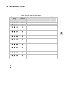
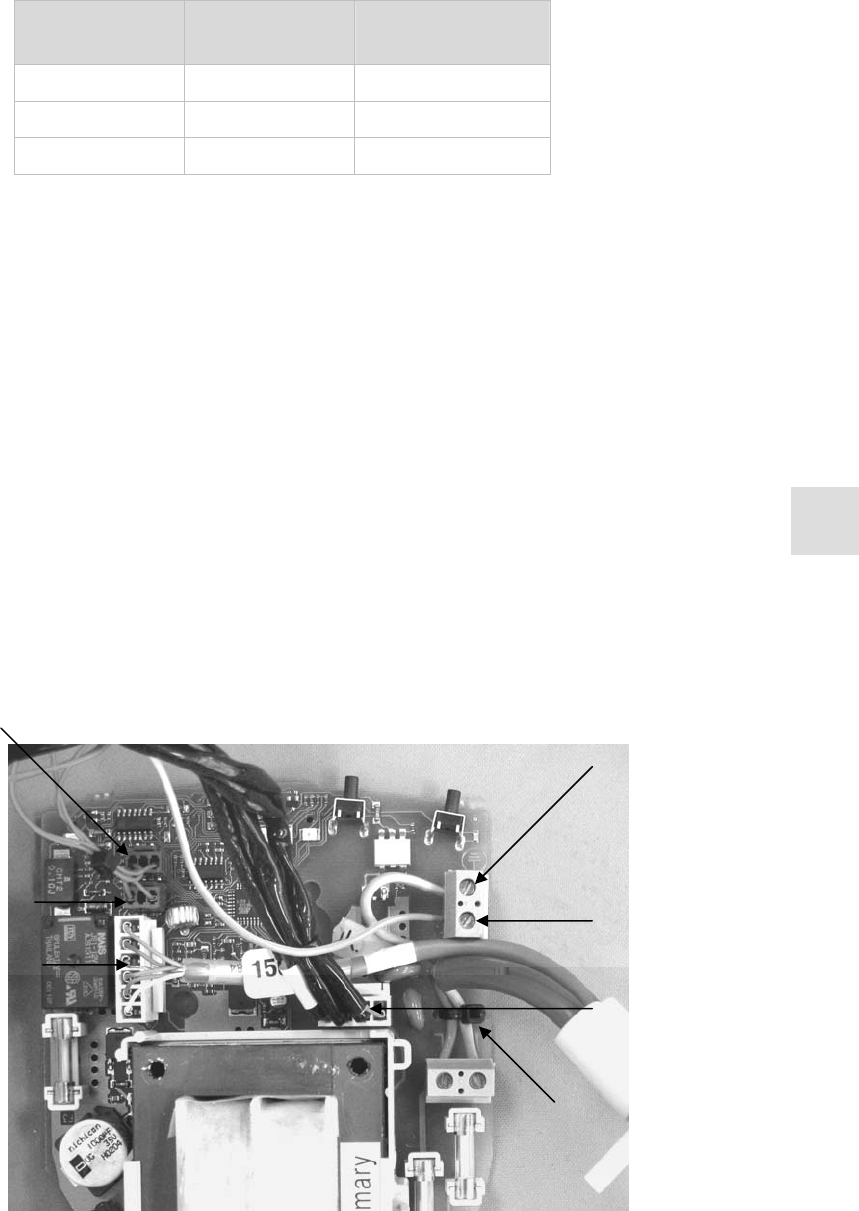
6.4 REPLACING THE PCB
Table 5 : Spare PCB part numbers
Model Supply Voltage PCB
Part Number
MR810A-- 230 V~ 043 0 42 232
MR810J-- 115 V~ 043 0 42 233
MR810G-- 100 V~ 043 0 42 234
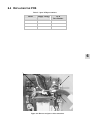
1. Open the case and remove the PCB (refer to § 6.2).
2. Cut the cable tie holding the phase and neutral conductors to the PCB (refer to Figure 6.4).
3. Slide the power cable and heater-wire adaptor clamp off the transformer support and lift away.
4. Unscrew the power cable (phase, neutral, and earth), and the heater plate earth connection.
5. Detach the heater-wire adaptor connector, the heater plate connector and the two heater plate thermistor
connectors (refer to Figure 6.4).
6. Unpack the replacement PCB and check that it is the correct voltage model from Table 5 above.
7. Reconnect the power cable, secure the phase and neutral wires to the PCB using a small (2.5 mm wide)
cable tie.
8. Screw the heater plate protective earth into the protective earth terminal block.
9. Reconnect the heater-wire adaptor, heater plate harness and two thermistors to their respective
locations.
Note: the primary and secondary th ermistors can be connected to either location on the PCB.
10. Slide the power cable and heater-wire adaptor clamp onto the transformer of the new PCB.
11. Reinstall the PCB, and close the case (refer to § 6.8).
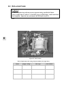
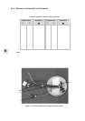
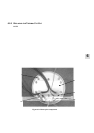
Figure 6.4: Harness and power cable connections
Heater Plate
protective earth
Mains protective
earth
Heater plate
connection
Cable tie
Primary
thermistor
connection
Secondary thermistor
connection
Heater wire adaptor
connection