


24
MR810 Technical Manual Rev C REF 185042601
6
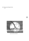
6.5.4 REPLACING THE HEATER PLATE THERMISTOR
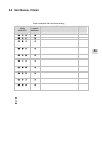
If the device has shown a thermistor fault, the resistance of the thermistor(s) can be checked at known
temperatures against the resistance-temperature table (Table 8 below).
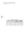
Table 8: Thermistor resistance temperature table
Temperature Resistance Temperature Resistance
°C °F
Ω
°C °F
Ω
5 41.0 22916 32 89.6 7676
10 50.0 18422 33 91.4 7398
15 59.0 14922 34 93.2 7133
20 68.0 12174 35 95.0 6878
21 69.8 11698 40 104 5756
22 71.6 11244 45 113 4843
23 73.4 10810 50 122 4098
24 75.2 10396 55 131 3484
25 77.0 10000 60 140 2977
26 78.8 9622 65 149 2556
27 80.6 9263 70 158 2204
28 82.4 8915 75 167 1908
29 84.2 8584 80 176 1660
30 86.0 8268 85 185 1449
31 87.8 7965 90 194 1269
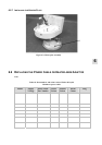
NOTE: Heater plate thermistor(s) will be required (part number 095 428 870).
1. Open the case and remove the PCB (refer to § 6.2).
2. Remove the heater plate (§ 6.5.2). Refer to Figure 8.2 for the exploded diagram.
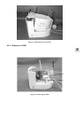
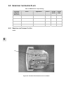
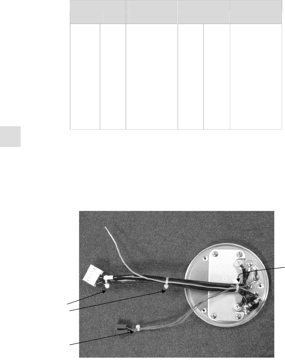
3. Cut the two cable ties securing the thermistors (refer to Figure 6.7).
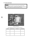
4. Remove the screw holding the heater plate thermistors (refer to Figure 6.8).
5. Place the new heater plate thermistor and screw it down.
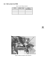
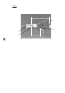
Figure 6.7: Location of cable ties securing heater plate harness
Orientati on o f
cable tie closest
to Heater Plate
Heater Plate
harness cable
ties
Thermistor
cable tie