


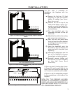
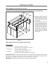
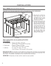
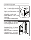

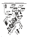

CERAMIC BAFFLE INSTALLATION:
1. Remove the front secondary air tube by placing a screwdriver (any style except at head) into one of
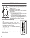
Left Ceramic
Baffle
Right Ceramic
Baffle
Figure 47: Installation of Ceramic
Bafe.
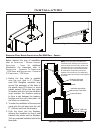
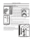
Installation
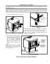
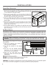
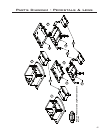
Figure 48: Fan Kit Wiring Diagram.
FAN WIRING DIAGRAM:
This appliance, when installed, must be electrically connected and grounded in accordance with local
codes or in the absence of local codes, with the current CSA C22.1 CANADIAN ELECTRICAL CODE. Part
1, SAFETY STANDARDS FOR ELECTRICAL INSTALLATIONS, or THE NATIONAL ELECTRICAL CODE ANSI
/ NFPA 70 in the USA.
CAUTION Label all wires prior to disconnection when servicing controls. Wiring errors
can cause improper and dangerous operation. Verify proper operation after servicing.
DO NOT cut or remove the grounding prong from the plug.
DO NOT route the power cord beneath the heater.
WARNING: This appliance is equipped with a three-prong (grounding) plug for your protection against
shock hazard and should be plugged into a properly grounded three-prong receptacle.
This is a basic wiring diagram for the option
fan installation.
1) Plug the fan assembly into a three (3)
prong (grounded) receptacle.
2) Turn the fan controller to the desired
setting.
3) Once the unit has reached operating
temperature, the fan temperature sensor
will turn the fan on automatically.
4) When the unit cools down the fan
temperature sensor will shut the fan off
automatically.
DO oil the fan bearings regularly.
the air holes and tapping it with a hammer/mallet to the left. Step
1 is only required on the insert models.
2. Slide the right ceramic bafe in over the secondary air tubes at the
top of the rebox. The tab must be on the top and pointing towards
the center and the smooth side is to face down.
3. Hook the outside edge of the bafe over the top of the secondary
air chamber. This will make room to for the installation of the left
ceramic bafe.
4. Slide the left ceramic bafe in over the secondary air tubes. The tab
must be on the bottom and pointing towards the center and the
smooth side is to face down.
5. Pull the bafes together in the middle so the right tab rests on top
of the left tab. Ensure the bafes are ush with the back and both
sides of the rebox.
38