


1
2
3
4
5
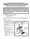
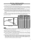
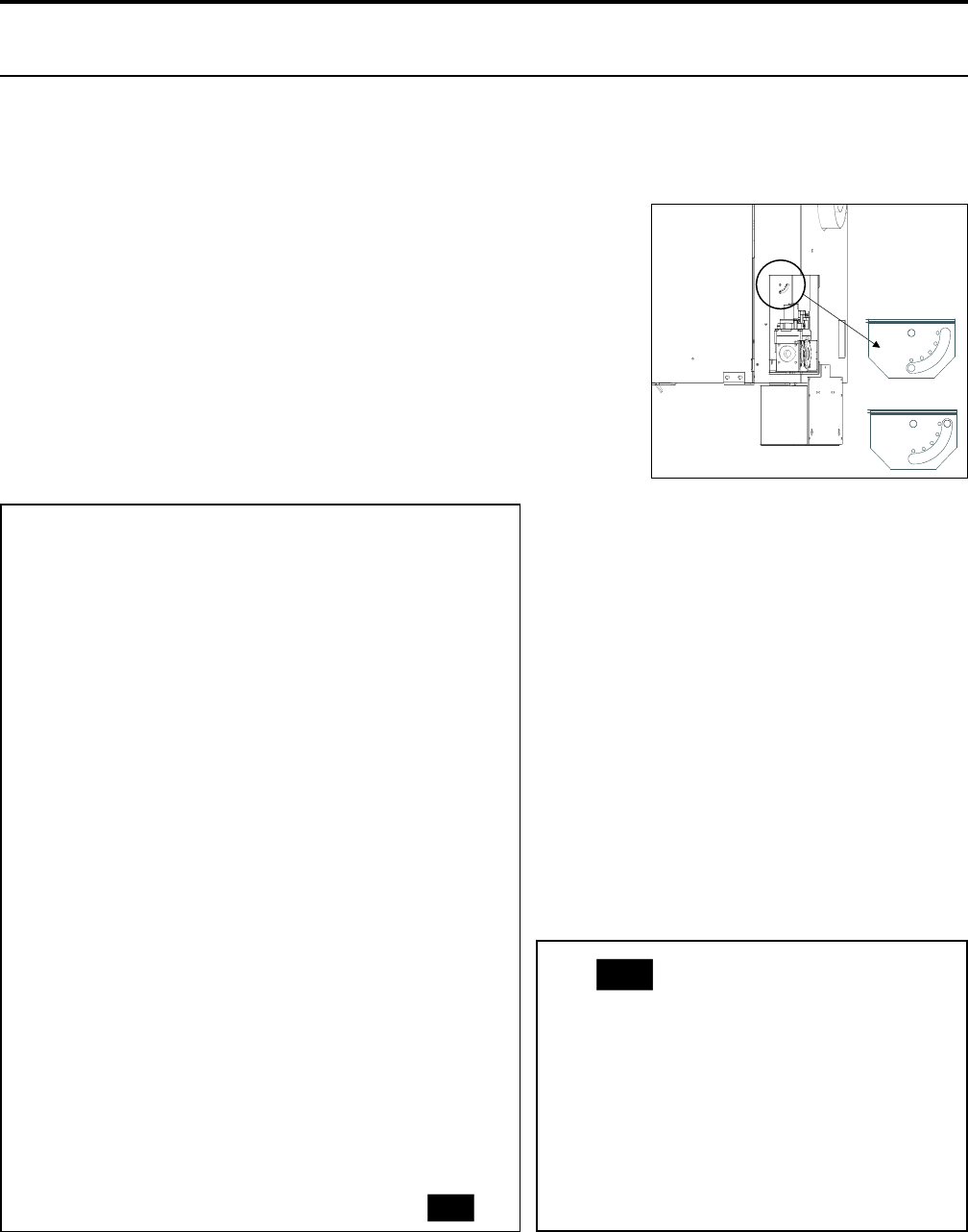
View showing fully
open restrictor plate
View showing fully
closed restrictor plate
1
2
3
4
5
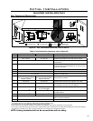
Figure 22: Restrictor plate settings.
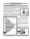
The ENVIRO WESTPORT has been designed with a built in restrictor
plate. The restrictor is designed to enhance ame appearance when
installing this unit with vertical chimneys as well as installations with
longer horizontal vent applications. It does this by controlling the
amount of air moving through the vent pipe.
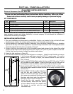
Figure 23 shows the vent restrictor position required, relative to the
length of vent pipe. Longer vertical vent lengths necessitate greater
restriction; position 1 is open and position 5 is maximum restriction
(refer to Figure 22). To avoid injury, it is best to make this adjustment
when the replace is cool or use welder’s gloves or oven mitts.
19
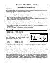
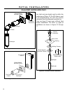
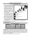
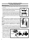
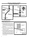
vent conFiguRations anD RestRictoR settings:
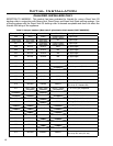
Figures 23 & 24 show the range of venting options, they show possible vent congurations if the unit is
top vented (see Figure 23) or rear vented (see Figure 24), for vertical and horizontal terminations, any
layout that remains within the shaded area is acceptable. Having the fewest number of elbows is ideal,
as they tend to disrupt air movement. Using 45˚ elbows is preferable to using 90˚ elbows. Also, a shorter
vent system will perform better than a longer one.
Initial Installation
QUALIFIED INSTALLERS ONLY
V
e
n
t
R
e
s
t
r
i
c
t
o
r
P
o
s
i
t
i
o
n
s
If top vented
the vent pipe
must rise a
minimum of
2’(0.61 m)
straight off the
top of the unit.
5
4
3
2
1
0’
(0 m)
0’
(0 m)
5’
(1.52 m)
5’
(1.52 m)
10’
(3.05 m)
10’
(3.05 m)
15’
(4.57 m)
15’
(4.57 m)
20’
(6.10 m)
25’
(7.62 m)
32’
(9.75 m)
30’
(9.14 m)
18’
(5.49 m)
Figure 23. Possible Vent Congurations for Top Vented;
Vertical and Horizontal Terminations.
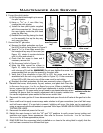
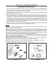
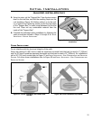
To access vent restrictor remove the valve
cover plate from the right rear corner of the
unit by undoing the two fastening screws.
Loosen the ¼” hex head screw and adjust to
the correct setting.
Slide the hex head screw to the next setting
and re-tighten the screw to secure in place.
The numbers in this chart represent the actual
vent restrictor settings. Although the numbers
do not appear on the unit use this as a guide
to follow.
Wait for unit to warm up to operating
temperature to ensure proper and clean
burning unit.
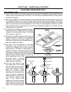
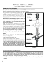
0’
(0 m)
2’max
(0.61 m)
Above 2’(0.61m)
vertical the rear
vent chart and
the top vent chart
are the same.
0’
(0 m)
5’
(1.52 m)
A 36”snorkel
must be used
if unit’s vent
termination
is in the dark
grey shaded
area.
5’
(1.52 m)
Figure 24. Possible Vent Congurations for Rear
Vented; Vertical and Horizontal Terminations.
Note: 0,0 in Figures 23 & 24 represent
the outlet of the ue collar elbow.