


25
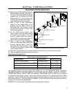
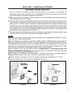
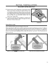
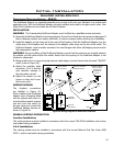
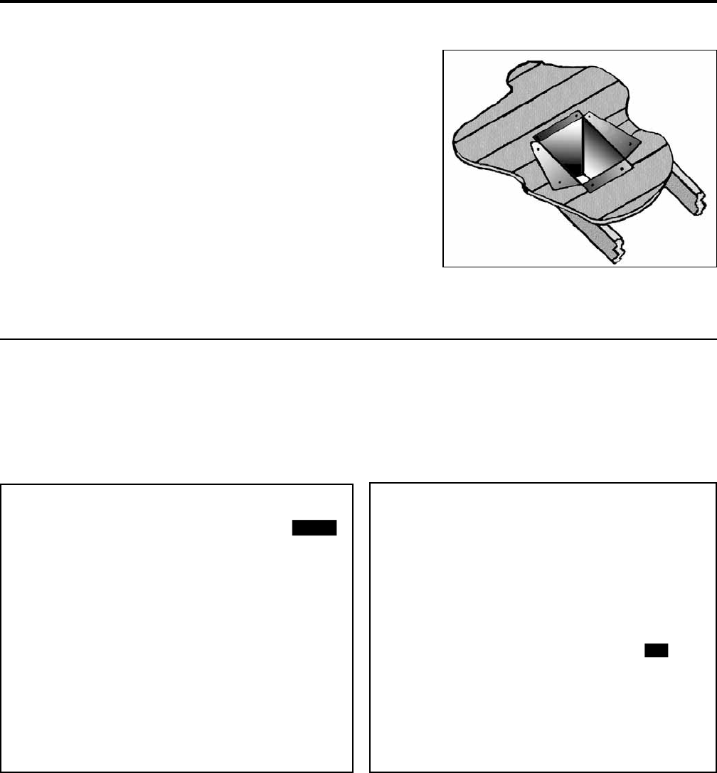
Figure 36: Cathedral Ceiling Support Box
Installation.
Initial Installation
QUALIFIED INSTALLERS ONLY
2
1
/2”
(67 mm)
Inside Wall
Outside Wall
36”(915 mm)
Snorkel
Outside Wall
Outside Wall
2
1
/2”
(67 mm)
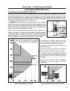
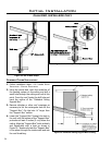
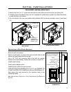
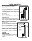
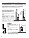
Figure 37: Corner installation rear vented with
snorkel.
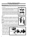
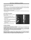
Figure 38: Corner installation top vented.
coRneR instaLLations:
Do not interfere with the structural integrity of the walls.
When rear venting if a 90° bend is used the maximum horizontal vent that can be used is 6” (152mm)
and if a 45° bend is used the maximum horizontal vent that can be used is 12” (305mm). For installations
with a 36” (915 mm) snorkel refer to Figure 37 and
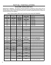
initial inStallation - vent confiGurationS and reStrictor
SettinGS. For other corner installations refer to Figure 38 and initial inStallation - vent confiGurationS and
reStrictor SettinGS.
5. Using tin snips, cut the “Support Box” from the top corners
down to the roof line, and fold the resulting aps over the
roof sheathing (Figure 36). Before nailing it in to the roof,
run a bead of non-hardening mastic around the top edges
of the “Support Box”, to make a seal between the box and
the roof. Clean out any combustible material from the
inside of the “Support Box”.
6. Complete the cathedral ceiling installation by following the
same procedures outlined in Steps 4 through 9 for
initial
inStallation - vertical inStallation.