


23
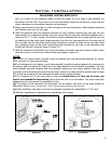
the support straps that extend out beyond the edge of the ashing.
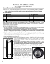
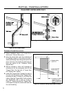
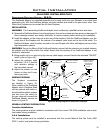
7. Slip the ashing over the pipe section protruding through the roof. Secure the base of the ashing to
the roof with roong nails. Use a non-hardening sealant between the uphill edge of the ashing and
the roof. Insure the roong material overlaps the top edge of the ashing as shown in Figure 30. Verify
that you have at least the minimum clearance to combustibles at the roof line.
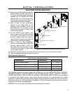
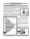
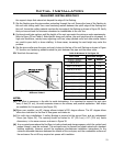
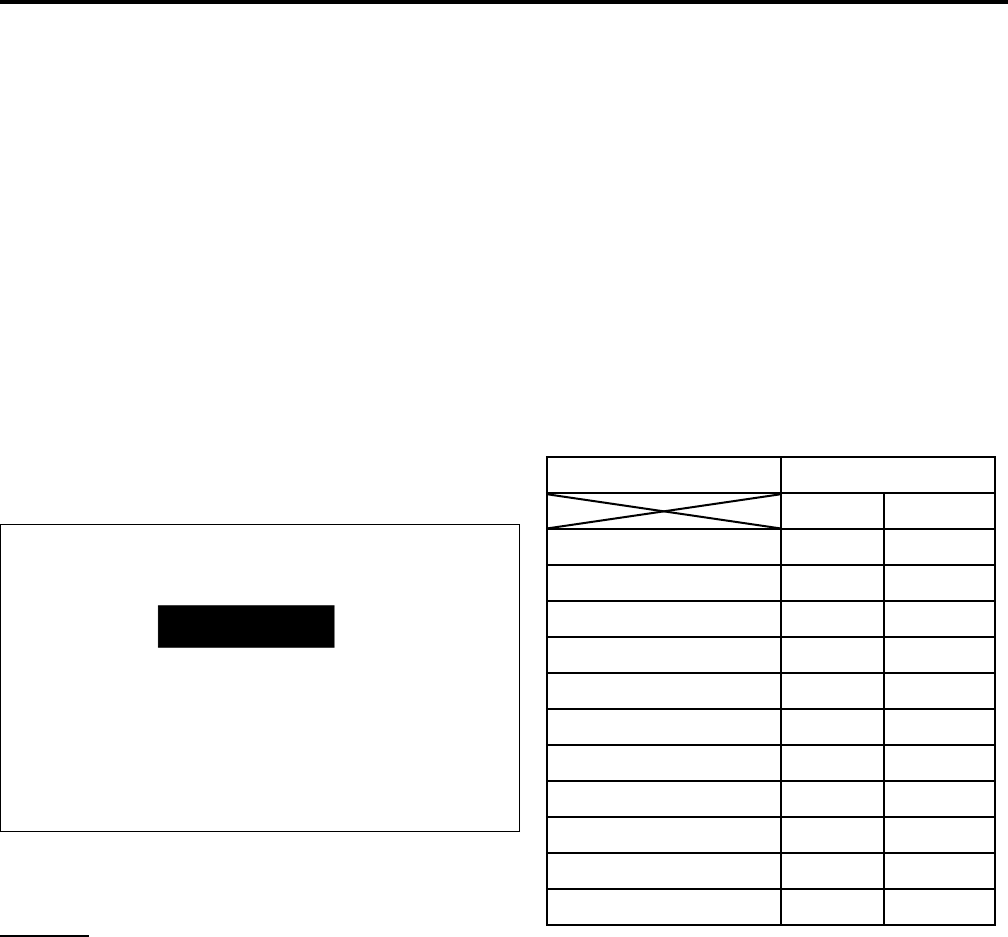
8. Continue to add pipe sections until the height of the vent cap meets the minimum code requirements.
Refer to Figure 32 and Table 6. Note that for steep roof pitches, the vent height must be increased. In
high wind conditions, nearby trees, adjoining roof lines, steep pitched roofs, and other similar factors
can result in poor draft, or down drafting. In these cases, increasing the vent height may solve the
problem.
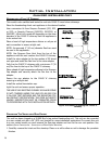
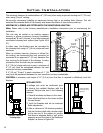
9. Slip the storm collar over the pipe, and push it down to the top of the roof ashing as shown in Figure
31. Use the non-hardening sealant around the joint between the pipe and the storm collar.
10. Twist-lock the vent cap.
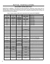
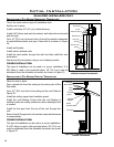
H
Dimension ‘H’ obtained
from table below.
Table 6: Minimum ‘H’ for Figure 32.
Roof Pitch Minimum Height
Feet Meters
Flat to 7/12 1 0.3
Over 7/12 to 8/12 1.5 0.46
Over 8/12 to 9/12 2 0.61
Over 9/12 to 10/12 2.5 0.76
Over 10/12 to 11/12 3.25 0.99
Over 11/12 to 12/12 4 1.22
Over 12/12 to 14/12 5 1.52
Over 14/12 to 16/12 6 1.83
Over 16/12 to 18/12 7 2.13
Over 18/12 to 20/12 7.5 2.29
Over 20/12 to 21/12 8 2.44
Figure 32: Height of Vertical Termination;
Reference Table 6.
NOTES:
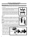
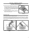
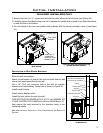
(a) If an offset is necessary in the attic to avoid obstructions, it is important to support the vent pipe
every 3 feet (91 cm), to avoid excessive stress on the elbows, and possible separation. Wall straps
are available for this purpose (see Figure 33).
(b) When ever possible, use 45° degree elbows instead of 90° degree elbows. The 45° degree elbow
offers less restriction to the ow of ue gases and intake air.
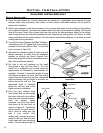
(c) For multi story installations. A ceiling restop is required at the second oor, and any subsequent
oors (see Figure 34). The opening should be framed to 10” (25.4 cm) x 10” (25.4 cm) inside
dimensions, in the same manner as shown in Figure 30.
(d) Any occupied areas above the rst oor, including closets and storage spaces, which the vertical vent
passes through, must be enclosed. The enclosure may be framed and sheet rocked with standard
building materials. However consult the appliance manufactures installation instructions for the
minimum allowable clearance between the outside of the vent pipe, and the combustible surfaces of
the enclosure. Do not ll any required air spaces with insulation.
Initial Installation
QUALIFIED INSTALLERS ONLY