


21
Initial Installation
QUALIFIED INSTALLERS ONLY
Wood screws (x4)
Cut vinyl siding
away to fit standoff
Bolt (x4)
required
Nut (x4)
required
Wood
screw (x4)
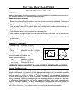
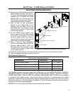
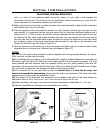
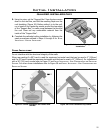
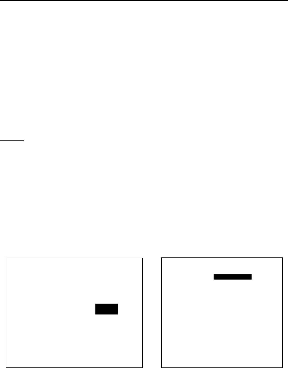
Figure 28: Installing Vent Cap with Vinyl Siding
Stand-Off.
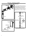
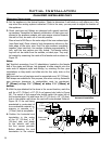
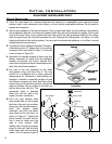
Figure 29: Installing Horizontal Vent
Termination.
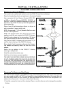
wall, run a bead of non-hardening mastic around the edges, so as to make a seal between the
termination and the wall. The arrow on the vent termination should be pointing up, insure that the
proper clearances to combustible materials are maintained.
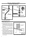
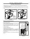
5. Before connecting the horizontal run of the vent pipe to the vent termination, slide the black decorative
wall thimble cover over the vent pipe.
6. Slide the appliance and vent assembly towards the wall, carefully inserting the vent pipe into the
cap assembly. It is important that the vent pipe extend into the vent cap a sufcient distance with a
minimum of 1¼” (3.2cm) overlap. Secure the connection between the vent cap pipe and the vent cap
by attaching the two sheet metal straps extending from the vent cap assembly into the outer wall of
the vent pipe. Use the two sheet metal screws provided to connect the straps to the vent pipe. Bend
any remaining portion of the sheet metal straps back towards the vent cap, so the decorative wall
thimble will conceal it (see left image in Figure 27).
7. Slide the decorative wall thimble up to the wall surface and attach with the screws provided. Apply
decorative brass or chrome trim if desired (see right image in Figure 27).
NOTES:
(a) The four (4) wood screws provided should be replaced with the appropriate fasteners for stucco,
brick, concrete, or other types of siding.
(b) For buildings with vinyl siding, a vinyl siding standoff, should be installed between the vent cap and
the exterior wall (see Figure 28). Attach the vinyl siding standoff to the horizontal termination. The vinyl
siding standoff prevents excessive heat from possibly melting the vinyl siding material. Note that the
horizontal vent termination bolts onto the at portion of the vinyl siding standoff (shaded area in Figure
28), so that an air space will exist between the wall and the vent termination.
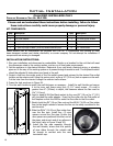
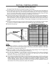
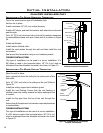
(c) The horizontal run of vent pipe must be level and should have a ¼ inch rise for every one
foot of run towards the termination. Never allow the vent to run downward. This could cause high
temperature and may present the possibility of a re.
(d) The location of the horizontal vent termination on the exterior wall must not be easily blocked or
obstructed. Refer to
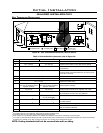
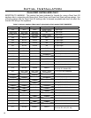
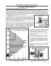
initial inStallation - vent confiGurationS and reStrictor SettinGS.
(e) When installing a vent pipe in a chase the minimum clearance to combustibles is 2” (51 mm).
(f) Maintain manufacturer’s clearances to combustibles with venting.