


Initial Installation
QUALIFIED INSTALLERS ONLY
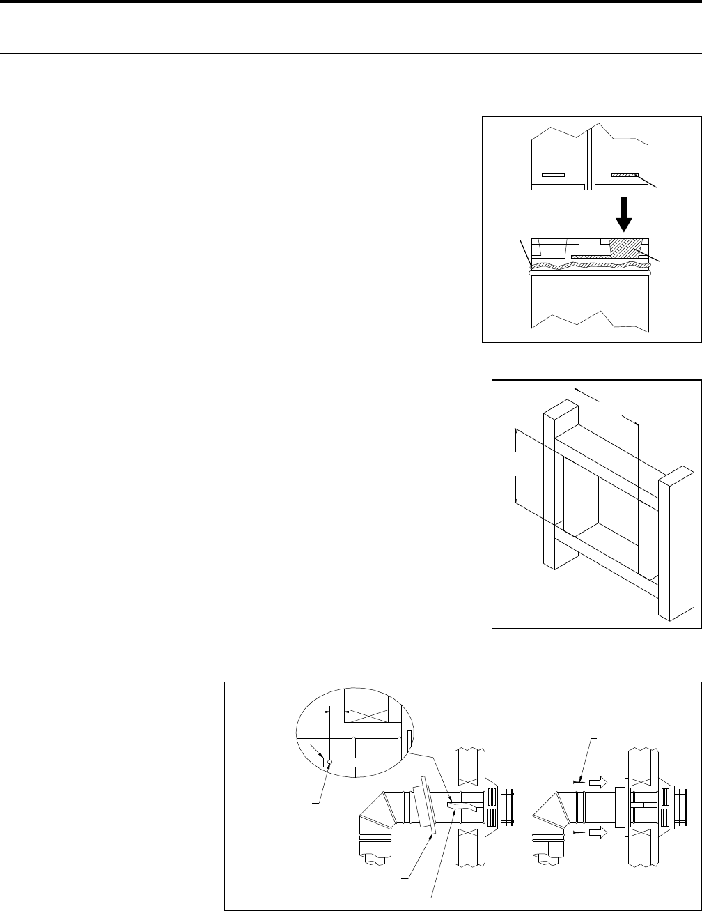
hoRizontaL instaLLation:
1. Set the appliance in the desired location. Check to determine if wall studs or roof rafters are in the
way when the venting system is attached. If this is the case, you may want to adjust the location of
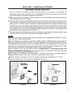
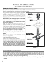
Sealant
Female
Locking
Lugs
Male
Locking
Lugs
Figure 25: Twist-Lock Connection
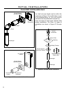
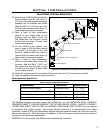
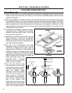
Woodscrews
Wall Thimble
Strap
Sheet metal
screws
Fold strap
here
1
1
/4"
(3.2cm)
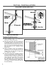
Figure 27: Installing Decorative Wall Thimble.
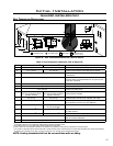
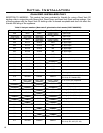
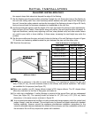
10"
(254mm)
10"
(254mm)
Figure 26: Wall Framing Hole for
Horizontal Installation.
the appliance.
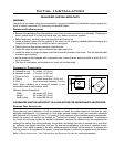
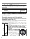
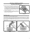
2. Direct vent pipe and ttings are designed with special twist-lock
connections. Assemble the desired combination of black pipe and
elbows to the appliance adapter with pipe seams oriented towards
the wall or oor, as much out of view as possible.
Place a bead of Mil-Pac on the outer edge of the inner exhaust pipe
(non-ared end). Place a bead of high temperature silicone on the
male edge of the outer pipe. Push the pipe sections completely
together, then twist-lock one section clockwise approximately ¼
turn, until the two sections are fully locked. The female locking
lugs will not be visible from the outside, on black pipe. They may
be located by examining the inside of the female ends as shown in
Figure 25.
Notes:
(a) Twist-lock procedure: four (4) indentations, located on the female
end of the pipes and ttings, are designed to slide straight onto the
male ends of adjacent pipes and ttings, by orienting the four pipe
indentations so they match and slide into the four entry slots on the
male end.
(b) Horizontal runs of vent pipe must be supported every 36” (915mm).
Wall straps are available for this purpose, also when running horizontal
pipe minimum clearances to combustibles must be maintained;
2” (51mm) at top, 1½” (38mm) at sides, 1½” (38mm) at
bottom.
3. With the pipe attached to the stove in the correct location, mark the
wall for a 10” (25.4cm) x 10” (25.4 cm) square hole (refer to Figure
26). The center of the square hole should match the center line of
the horizontal pipe. Cut and frame the 10” (25.4cm) x 10” (25.4cm)
hole in the exterior wall where the vent will be terminated. Refer to
20
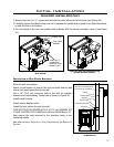
Figure 18. If the wall being
penetrated is constructed of
non-combustible material i.e.
masonry or concrete, a 7”
(17.8cm) hole is acceptable.
4. Position the horizontal vent
termination in the center
of the 10” (25.4cm) x 10”
(25.4cm) hole, and attach
to the exterior wall with
the four screws provided.
Before attaching the vent
termination to the exterior