


Initial Installation
QUALIFIED INSTALLERS ONLY
WARNING:
Operation of this heater when not connected to a properly installed and maintained venting system can
result in carbon monoxide (CO) poisoning and possible death.
PRePaRation FoR instaLLation:
• Remove the packaging from the appliance, and check to make sure there is no damage. If damage is
found, please report it to both the carrier and your dealer as soon as possible.
• Before beginning, carefully check the glass door and the log set
• Locate a position where the ue system of the stove can be properly installed without damaging the
integrity of the building; e.g. cutting a wall or ceiling joist.
• Check stove and ue system clearance requirements.
• Locate the stove where it can be accessed by a gas supply line.
• Locate the stove in a large and open room that is centrally located in the house. This will optimize heat
circulation and comfort.
• As the stove can be equipped with a convection fan, ensure that an electrical outlet is within 6 ft (1.8
m) of the stove.
• The ow of combustion and ventilation air must not be obstructed.
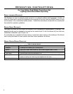
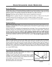
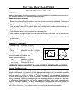
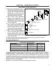
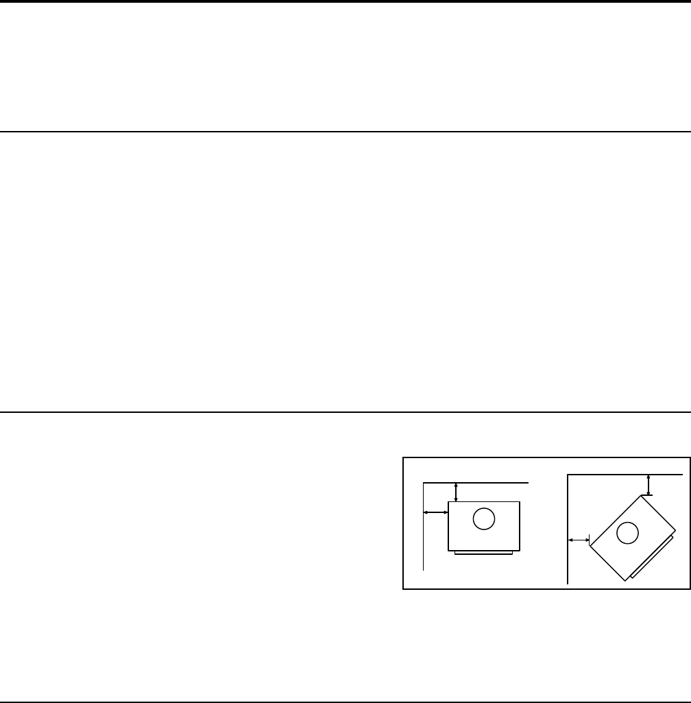
cLeaRances to combustibLes:
A. Sidewall to unit 11 inches (27.9 cm)
B. Backwall to unit 2.5 inches (6.35 cm)
C. Corner to unit 2.5 inches (6.35 cm)
D. Ceiling 60 inches above oor (152.4 cm)
E. Floor (hard wood and linoleum) 0 inches
Note: When installing on a carpeted surfaces a non-
combustible hearth pad must be used.
Minimum Alcove Dimensions:
Width 48 inches (121.9 cm)
Height 60 inches (152.4 cm)
Depth (max) 24 inches (60.96 cm)
CLEARANCES MUST BE SUFFICIENT TO ALLOW ACCESS FOR MAINTENANCE AND SERVICE.
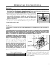
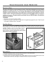
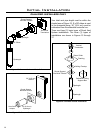
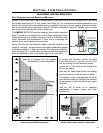
PLanning youR instaLLation:
When planning your installation, it will be necessary to select the proper length of vent pipe for your
particular requirements. It is important to note when passing through a wall, the maximum allowable
wall thickness is 10 inches (25.4 cm), 1½ inches (3.8 cm) clearance to combustibles must be maintained.
Select the amount of vertical rise desired for “vertical-to-horizontal” type installations. To determine
the length of vent pipe required for vertical installations, measure the distance from the appliance ue
outlet to the ceiling, the ceiling thickness, the vertical rise through the attic or second story, and allow
for sufcient vent height above the roof line. For two story applications, a re stop is required at each
oor level. If an offset is needed in the attic, additional pipe and elbows will be required. To connect the
venting system to the appliance ue outlet, a twist-lock adapter is built into the appliance at the factory.
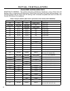
Refer to initial inStallation - vent confiGuration and reStrictor SettinGS for venting parameters.
B
A
Front
Back wall
Side wall
C
C
Front
Adjacent wall
Adjacent wall
Figure 14: Clearances to combustibles.