


Page 4917375-6-0705
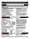
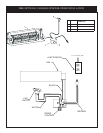
CAUTION: ALL WIRING SHOULD BE DONE BY A QUALIFIED ELECTRICIAN AND SHALL BE IN COMPLIANCE
WITH ALL LOCAL, CITY AND STATE BUILDING CODES. BEFORE MAKING THE ELECTRICAL CONNECTION,
MAKE SURE THAT MAIN POWER SUPPLY IS DISCONNECTED. THE APPLIANCE, WHEN INSTALLED, MUST BE
ELECTRICALLY GROUNDED IN ACCORDANCE WITH LOCAL CODES OR, IN THE ABSENCE OF LOCAL CODES,
WITH THE NATIONAL ELECTRICAL CODE ANSI/NFPA 70 (LATEST EDITION).
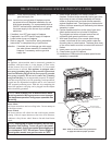
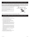
A factory installed junction box is located on the lower right side
of the fireplace. Wiring must be fed to the junction box and
attached to the receptacle that is provided. Leave approximately
6" of wire in the junction box for connection.
Attach black wire to one side of the receptacle and white wire to
opposite side of receptacle. The ground wire should be attached
to the green (ground) screw.
Install the receptacle into the junction box. Attach cover plate.
JUNCTION BOX WIRING INSTALLATION INSTRUCTIONS
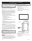
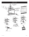
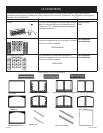
OPTIONAL BRICK LINER INSTALLATION INSTRUCTIONS
1. Using gloves, unpack liner components and check for
damaged or missing components.
2. Lower bottom louver and remove upper louver on fireplace.
3. Remove glass frame assembly from fireplace.
4. Remove rear logs from burner assembly.
5. Place brick panel (rear) against rear wall in fireplace.
Note:The top edge will have a half-moon cutout relief to
match up with the rear flue vent hole.
6. While holding finished edge on brick panel (side), place
brick panel (sides) against side walls in fireplace. Move side
panels rearward until the back edge meets the rear brick
panel. Slide side brick panels down so they rest on firebox
bottom.
7. Align grout lines on top brick panel with the grout lines on
the side brick panels. Place the top brick panel into brick
panel holder. With needle-nose pliers, carefully bend hold-
down tabs on brick panel holder over the edges of the top
brick panel. The hold-down tabs will securely hold the top
brick panel in place.
8. Replace rear logs onto burner assembly. (Refer to log
placement, page 28.)
9. Attach glass frame assembly onto fireplace.
10. Raise bottom louver and replace top louver onto fireplace.
11. Installation of optional brick liner is complete.
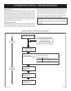
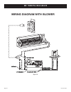
*Note: For intermittent pilot models, refer to wiring instructions on page 34.
*