


Page 30 17375-6-0705
STANDING PILOT OPERATING INSTRUCTIONS
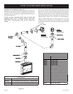
REMOTE/OFF/ON Switch
The fireplace is equipped with a REMOTE/OFF/ON switch. A
wire harness is attached to the REMOTE/OFF/ON switch. The
red, black and green (wires) female push-ons attach to the RE-
MOTE/OFF/ON switch. At the opposite end of the wire harness,
the black and green (wires) female push-ons attach to the gas valve.
An additional green wire and the red wire, which are stripped and
bare, will attach to one of the accessories that can be purchased
for use with your fireplace.
Operation of REMOTE/OFF/ON Switch with no
Accessories
To ignite main burner, turn the control knob on the gas valve
from the PILOT position to the ON position. Turn the REMOTE/
OFF/ON switch from the OFF position to the ON position. The
additional green wire and red wire, which are stripped and bare
are not used.
Wall Switch, FWS-1
Connect the green and red, stripped and bare, wires on the
REMOTE/OFF/ON switch wire harness to the wall switch. Turn
the REMOTE/O
FF/ON switch to the REMOTE position. Pivot
the rocker switch on the FWS-1 to the ON position.
Wall Thermostats (optional)
TRW - Wireless for Millivolt models
TMV - Reed switch for Millivolt models
Battery Operated Remote Controls, FRBC, FBRTC, and
TRW
Connect the green and red, stripped and bare, wires on the
REMOTE/OFF/ON switch wire harness to the remote receiver
that is a component in the remote kit. Turn the REMOTE/OFF/ON
switch to the REMOTE position. Follow instructions included
with the remote to complete installation.
Note: If batteries fail in the remote, and immediate heat is desired,
turn the REMOTE/OFF/ON switch from the REMOTE position
to the ON position.
Electric (120 volt) Operated Remote Control, FREC
Connect the green and red, stripped and bare, wires on the
REMOTE/OFF/ON switch wire harness to the wires on remote
receiver that is a component in the FREC. Turn the REMOTE/
OFF/ON switch to the REMOTE position. Follow instructions in
the FREC to complete installation.
NOTE: If electric (120 colt) fails in FREC, and immediate heat is
desired, turn the REMOTE/OFF/ON switch from the REMOTE
position to the ON position.
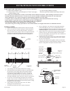
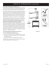
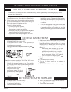
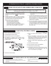
Installation of Remote Receiver
Place remote receiver on the floor of fireplace behind the louver
as far forward as possible.
Attention: The velcro loop and hook are not necessary in this
installation but can be used to secure remote receiver.
Refer to remote control installation and operating instructions for
more details on remote control.
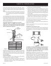
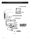
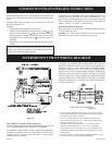
Millivolt Control
The valve regulator controls the burner pressure which should be
checked at the pressure test point. Turn captured screw counter
clockwise 2 or 3 turns and then place tubing to pressure gauge
over test point (Use test point “A” closest to control knob). After
taking pressure reading, be sure and turn captured screw clockwise
firmly to re-seal. Do not over torque. Check for gas leaks.
Millivolt thermopile is self generating. Gas valve does not require
24 volts or 110 volts.
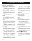
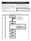
Check System Operation
Millivolt system and all individual components may be checked
with a millivolt meter 0-1000 MV range.
It is important to use wire of a gauge proper for the length of the
wire:
Recommended Wire Gauges
Maximum Length Wire Gauge
1' to 10' 18
10' to 25' 16
25' to 35' 14
OPERATING INSTRUCTIONS (continued)