


Page 1517375-6-0705
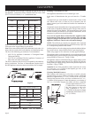
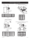
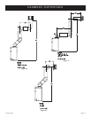
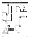
Figure 21
Examples of possible venting systems using two (2) 90° elbows. V
is listed as minimum vertical dimensions and H1 + H2 is listed as
total of maximum horizontal dimensions. The maximum vertical
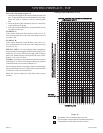
and horizontal distances for two (2) 90° elbows as shown in
Figure 22 is 20 feet.
Attention: Refer to Figure 19 for additional venting
requirements.
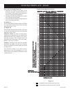
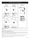
Figure 22
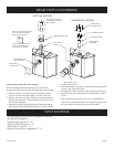
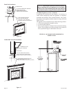
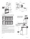
Below Grade Installation
When it is not possible to meet the required vent terminal clearances
of 12" (305mm) above grade level, a snorkel kit is recommended.
It allows installation depth down to 7" (178mm) below grade level.
The 7" (178mm) is measured from the center of the horizontal
vent pipe as it penetrates through the wall.
Ensure the sidewall venting clearances are observed. If venting
system is installed below ground, we recommend a window
well with adequate and proper drainage to be installed around
the termination area.
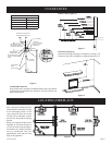
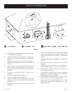
TYPICAL BASEMENT INSTALLATION
Figure 20
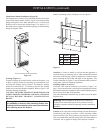
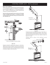
Examples of possible venting systems using one (1) 90° elbow.
Eight (8) feet is listed as minimum vertical vent run with 20 feet
of maximum horizontal vent run. Vertical dimensions are based on
centerline to centerline of pipe. Horizontal dimensions are based
on centerline of pipe to end of termination.
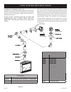
VENTING FIREPLACE - TOP (continued)
Firestop at
Ceiling Level
Firestop at
Ceiling Level