


Page 2317375-6-0705
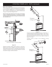
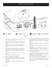
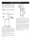
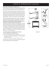
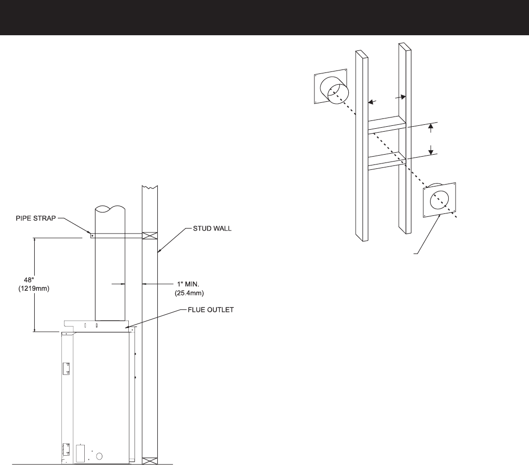
Installing Support Brackets (Figure 37)
A horizontal pipe support MUST BE used for each 3 feet of
horizontal run. The pipe supports should be placed around the
pipe and nailed in place to framing members. There MUST BE
a 3 inch clearance to combustibles above 8 inch diameter pipe
and elbows and 1 inch clearance on both sides and bottom of the
8 inch dia. pipe to combustibles on all horizontal pipe sections
and elbows.
Vertical runs of this vent systems must be supported every 4 feet
above the appliance flue outlet by wall brackets attached to the
8 inch vent pipe and secured with nails or screws to structural
framing members.
Figure 37
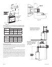
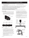
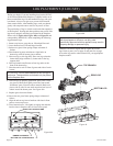
Installing Firestops (Figures 38, 39, 40 and 41)
Firestops are required for safety whenever the vent system passes
through an interior wall, an exterior wall, or a ceiling. These
firestops act as a firebreak heat shield and as a means to insure that
minimum clearances are maintained to the vent system.
Horizontal runs in the vent system which pass through either
interior or exterior walls, require the use of wall firestops on both
sides of the wall through which the vent passes.
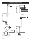
Cut a 10-3/8 inch x 12-3/8 inch hole in wall. Position firestop
(SD1249) on interior side of wall for 10-3/8 inch x 12-3/8 inch
hole.
Attention: Wall firestop hole is off-set towards bottom of wall
opening. Secure with nails or screws. Continue the vent run through
the firestop (See Figure 38).
FRAMING AND FINISHING
10
3/8
12 3/8
WALL FIRESTOP
HOLE IS OFF-SET
TO
WARDS BOTTOM
OF
WALL OPENING.
Figure 38
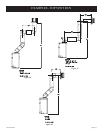
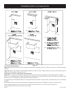
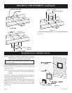
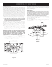
Vertical runs of this system which pass through ceilings require the
use of ONE (1) ceiling firestop at the hole in each ceiling through
which the vent passes.
Position a plumb bob directly over the center of the vertical vent
component and mark the ceiling to establish the center point of the
vent. Drill a hole or drive a nail through this center point and check
the floor above for any obstructions such as wiring or plumbing
runs. Reposition the appliance and vent system, if necessary, to
accommodate ceiling joists and/or obstructions.
Cut a 10 1/2 inch x 10 1/2 inch hole through the ceiling, using
the center point previously marked. Frame the hole with framing
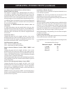
lumber the same size as the ceiling joists. (See Figure 39) If the
area above the ceiling is NOT an attic, position and secure the
ceiling firestop (SD-1263) on the ceiling side of the previously cut
and framed hole. (See Figure 40) If the area above the ceiling is
an attic, position and secure the firestop on top of the previously
framed hole. (See Figure 41)
NOTE: Remove insulation from the framed area in the attic before
installing the firestop and/or vent pipes.