


Page 1117375-6-0705
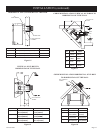
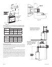
Note: For finishing to top of fireplace, refer to Figure 12.
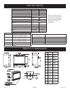
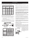
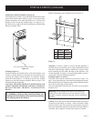
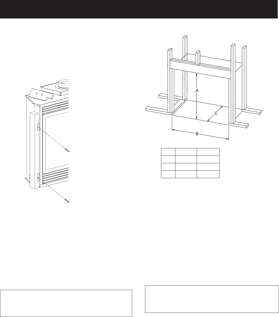
DVP42 DVP48
"A" 37 3/4" 37 3/4"
"B" 43 3/8" 49 3/8"
"C" 19 7/8" 19 7/8"
Figure 11
Attention: If a base or mantel is not used and the appliance is
installed directly on carpeting, tile or other combustible material
other than wood flooring, it shall be installed on a metal or wood
panel extending the full width and depth of the appliance. The
vertical dimension in Figure 11 must be adjusted when a metal or
wood panel is placed beneath the appliance.
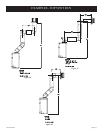
Finishing (Figures 12 and 13)
Finish the walls with the material of your choice. Figure 3 on
page 7 shows the minimum vertical and corresponding maximum
horizontal dimensions of mantels or other combustible projections
above the top front edge of the fireplace.
Only non-combustible materials may be used to cover the black
fireplace front.
Warning: When finishing the fireplace never obstruct or
modify the air inlet/outlet louvers in any manner. Provide
adequate clearances around air openings into the combustion
chamber.
Caution: If the joints between the finished wall and the fireplace
surround (top and sides) are sealed, a 300°F minimum sealant
material must be used. These joints are not required to be sealed.
Only non-combustible material (using 300°F minimum adhesive
if needed), can be applied as facing to the fireplace surround.
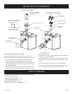
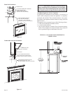
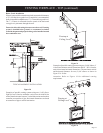
Flush Mount Mantel Installation (Figure 10)
The fireplace must extend 3/4" beyond finished wall surface when
using a flush mount mantel. Refer to Figure 10 to locate nailing
flanges on fireplace sides. Mark and drill two (2) 1/8" holes into
fireplace side to mount each nailing flange. Use eight (8) 1/2"
hex-head screws supplied in hardware package to attach nailing
flanges to fireplace sides.
Figure 10
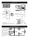
Framing (Figure 11)
Fireplace framing can be built before or after the fireplace is set
in place. Framing should be positioned to accommodate wall
covering and fireplace facing material. The fireplace framing
should be constructed of 2 x 4 lumber or heavier. The framing
headers may rest on the fireplace standoffs. Refer to Figure 11 for
minimum framing dimensions.
CAUTION: MEASURE FIREPLACE DIMENSIONS AND
VERIFY FRAMING METHODS, AND WALL COVERING
DETAILS BEFORE FRAMING CONSTRUCTION
BEGINS.
Framing dimension "A" includes a three inch clearance
for standoffs on firebox. After installing firebox into
framing, the finished wall surface must cover the three
inch opening above the firebox.
INSTALLATION (continued)
NAIL OR OTHER SUITABLE FASTENER