


Page 4717375-6-0705
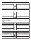
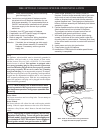
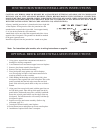
FBB4 OPTIONAL VARIABLE SPEED BLOWER INSTALLATION
Attention: Install blower assembly before connecting
gas inlet supply line
Note: Junction box on right side of fireplace must be
pre-wired at time of fireplace installation for use
with blower assembly. It is recommended that an
ON/OFF wall switch be installed that will activate
the power supply to the furnace by a qualified
electrician.
1. If installed, turn OFF gas supply to fireplace.
2. If applicable, turn OFF electric supply to fireplace.
3. Lower bottom louver on fireplace.
4. Refer to page 48, "Junction Box Wiring Installation
Instructions" to complete wiring of junction box.
Attention: If installed, do not damage gas inlet supply
line when blower assembly is inserted into
fireplace. If necessary, remove gas inlet
supply line.
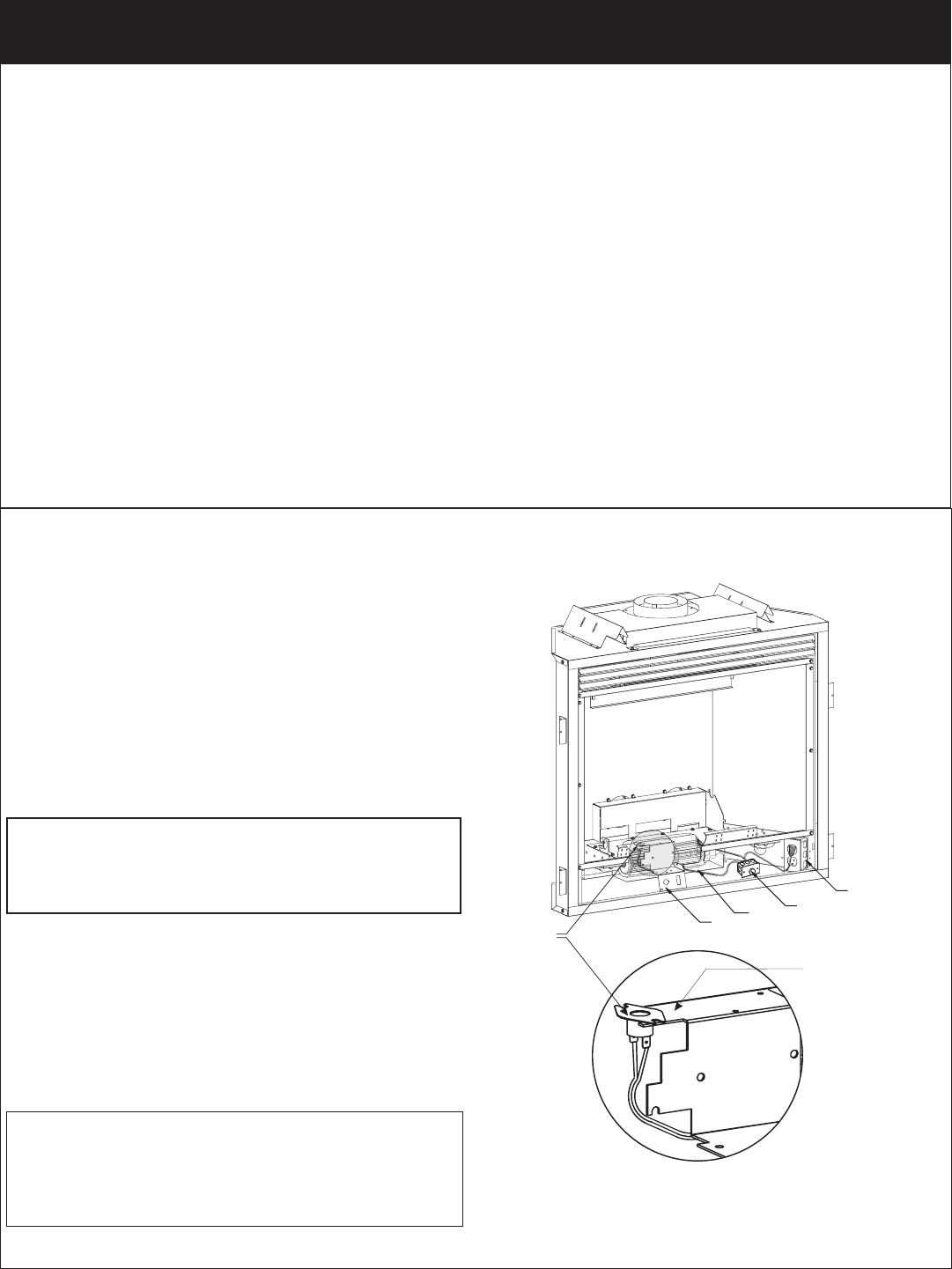
5. Insert blower assembly into interior, bottom of
fireplace. Position blower assembly behind gas valve,
align notch on back of blower assembly with center
screw on fireplace back and push blower assembly
against fireplace back. The magnets on the back and
bottom of blower assembly will sufficiently hold blower
assembly in place.
6. Position speed control box to the right of gas valve.
Attach speed control box to bottom of fireplace.
The magnets on bottom of speed control box will
sufficiently hold speed control box in place.
7. With base (flush face) of fan control switch facing
upward, insert base of fan control switch under the
mounting tabs on valve bracket. The base (flush face)
of fan control switch must be in contact with bottom of
firebox.
8. Insert power cord plug into junction box.
9. Close bottom louver on fireplace.
10. Installation of FBB4 optional variable speed blower
assembly is completed.
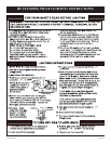
Wiring
The appliance, when installed, must be electrically grounded in
accordance with local codes or, in the absence of local codes,
with the National Electrical Code, ANSI/NFPA 70, if an external
electrical source is utilized. This appliance is equipped with a
three-prong [grounding] plug for your protection against shock
hazard and should be plugged directly into a properly grounded
three-prong receptacle. Do not cut or remove the grounding
prong from this plug. For an ungrounded receptacle, an adapter,
which has two prongs and a wire for grounding, can be purchased,
plugged into the ungrounded receptacle and its wire connected
to the receptacle mounting screw. With this wire completing the
ground, the appliance cord plug can be plugged into the adapter
and be electrically grounded.
Caution: Label all wires prior to disconnection when
servicing controls. Wiring errors can cause improper
and dangerous operation. Verify proper operation after
servicing.
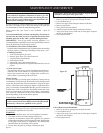
Blower Motor
The blower motor does not have oiling holes. Do not attempt to
oil the blower motor.
Blower Wheels
The blower wheels will collect lint and could require periodic
cleaning. If the air output decreases or the noise level increases,
it indicates a dirty blower wheel. Remove fan and clean blower
wheels.
Warning: Unplugging of blower accessory will not stop
the heater from cycling. To turn off gas to the heater
(millivolt model): push in gas control knob slightly and
turn clockwise to "OFF." Do not force. To turn off gas on
direct ignition model, turn gas line valve to "OFF."
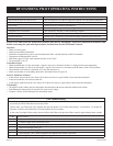
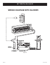
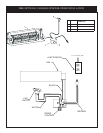
VALV
EBRACKET
F
ANSWITCH
FA
NKIT
SPEEDCONTROL
JUNCTIONBOX
SWITCH
HOLDER
(TOPOFVALV
EBRACKET)
SEE NOTE*
*Note: Refer to Junction Box wiring instructions
on page 34 and 48 for proper operation.