


Page 34 17375-6-0705
The intermittent pilot (120/24 volt system) is ON when the main
burner is ON. When the main burner is OFF the intermittent pilot
is OFF.
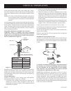
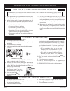
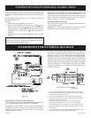
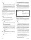
The pilot flame should envelop 3/8 to 1/2 inch (10 to 13mm) of
the tip of the flame rod.
To adjust:
1. Remove the pilot adjustment cover screw.
2. Turn the inner adjustment screw clockwise
to de-
crease or counterclockwise
to increase pilot flame.
Pilot adjustment is shipped at full flow rate. Turn the inner
adjustment screw clockwise
if the inlet pressure is
too high.
3. Replace the cover screw after the adjustment to prevent gas
leakage.
Label all wires prior to disconnection when servicing controls.
Wiring errors can cause improper and dangerous operation.
Verify proper operation after servicing.
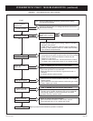
Figure 54
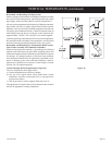
INTERMITTENT PILOT OPERATING INSTRUCTIONS
Provided on the intermittent pilot wiring harness are two (2)
stripped and bare wires that are labeled THERMOSTAT. The
wires will be used for attachment of 24 volt thermostat, optional
FWS-1 wall switch or will attach into the receiver on an optional
FRBC-1, FRBTC-1 or FREC-1 remote control.
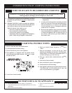
Installation of Remote Receiver
Place remote receiver on the floor of fireplace behind the louver
as far forward as possible.
Attention: The velcro loop and hook are not necessary in this
installation but can be used to secure remote receiver.
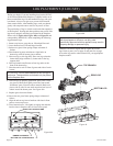
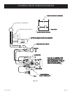
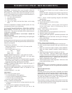
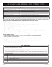
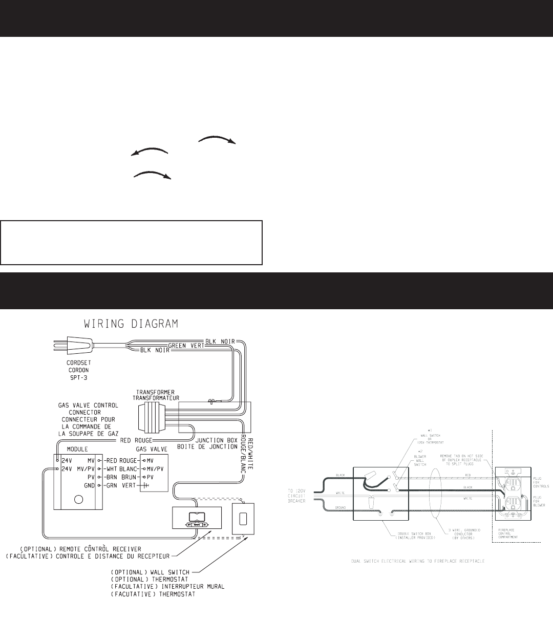
INTERMITTENT PILOT WIRING DIAGRAM
ELECTRICAL CONNECTION (Figure 55)
The DVP Intermittent Pilot Models with optional fan requires 120
VAC electrical hookup to the electrical box (installed).
The appliance, when installed, must be electrically grounded in
accordance with local codes or, in the absence of local codes,
with the National Electrical Code, ANSI/NFPA 70, if an external
electrical source is utilized.
CAUTION: ALL WIRING SHOULD BE DONE BY A QUALI
-
FIED ELECTRICIAN AND SHALL BE IN COMPLIANCE
WITH ALL LOCAL, CITY AND STATE BUILDING CODES.
BEFORE MAKING THE ELECTRICAL CONNECTION,
MAKE SURE THAT MAIN POWER SUPPLY IS DISCON
-
NECTED. THE APPLIANCE, WHEN INSTALLED, MUST
BE ELECTRICALLY GROUNDED IN ACCORDANCE WITH
LOCAL CODES OR, IN THE ABSENCE OF LOCAL CODES,
WITH THE NATIONAL ELECTRICAL CODE ANSI/NFPA 70
(LATEST EDITION).
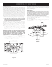
Figure 55
1. To wire Junction Box Receptacle, remove the tab on the side of
the receptacle (hot side) to split receptacle. This will be required
to separate blower and valve circuits.
2. Power for switched and live sides of Duplex Receptacle must
come from the same power source. (One circuit breaker on main
panel must switch all power off.)
3. From the wall box to the fireplace a 3-wire conductor with
ground is recommended, however (2) two-wire conductors
with grounds may be used in place of a 3-wire conductor with a
ground if the black wires from the thermostat and blower switch
are identified.
4. Two wall switches, or a wall switch and thermostat may be used
to activate the two receptacle plugs independently.