


Page 36 17375-6-0705
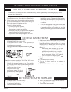
GENERAL: All fireplaces have been fire-tested to check for
proper operation. This includes, main burner flame, pilot flame,
fan operation, fan control, limit control and automatic valve op-
eration. If the fireplace fails to function on initial installation, it
is advisable to re-check the following:
1. 115 volts to the junction box.
2. Inlet gas pressure.
3. The 24 volt system.
4. Type of gas being used and that shown on the rating
label.
The Service Department at Empire Comfort Systems, Inc. may
be contacted to assist in servicing furnace.
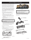
Servicing the Pilot and Main Burners, Pilot Orifice, and Main
Burner Orifices: Disconnect the gas supply at the inlet to the
control valve. Then remove the burner door to which the above
components are attached.
S8600H INTERMITTENT IGNITION MODULE
SPECIFICATIONS
Lockout timing is 90 seconds. Ignition timing is until pilot lights
or lockout occurs.
Module shuts down and cuts power to gas control on flame failure.
Gas control closes to provide 100 percent lockout on flame failure.
Manual reset required.
ELECTRICAL RATINGS:
Voltage and frequency: 20.5 to 28.5V (24V nom.) 60 Hz.
Current rating: 0.2 A.
Valve contact ratings (at 24 Vac):
Run Inrush
Pilot 1.0 A 10.0 A
Main 1.0 A 10.0 A
SPARK GENERATOR OUTPUT: 13kV peak at 25 pf load.
THERMOSTAT ANTICIPATOR SETTING: 0.2 A plus pilot
valve rating plus main valve rating.
THERMOSTAT COMPATIBILITY: Standard models compatible
with all open-close switch type 24 Vac thermostats capable of
supplying rated voltage and current to the module.
AMBIENT TEMPERATURE RATING: Minus 40 F to plus 175
F (minus 40 C to plus 79 C).
RELATIVE HUMIDITY RATING: 5 to 90 percent RH at 95 F.
FLAME FAILURE RESPONSE TIME: 0.8 seconds at 1.0 uA
flame current.
FLAME CURRENT: 1 uA, min.
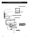
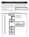
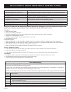
CHECKOUT
Check out the gas control system:
1. At initial installation of the appliance.
2. As part of regular maintenance procedures.
3. As the first step in troubleshooting.
4. Any time work is done on the system.
STEP 1: Perform Visual Inspection.
A. With power off, make sure all wiring connections are clean
and tight.
B. Turn on power to appliance and ignition module.
C. Open manual shutoff valves in the gas line to the
appliance.
D. Do gas leak test ahead of gas control if piping has been
disturbed.
GAS LEAK TEST: Paint pipe joints with rich soap and water
solution. Bubbles indicate gas leak. Tighten joints to stop
leak.
STEP 2: Review Normal Operating Sequence and Module
Specifications.
STEP 3: Reset the Module.
A. Turn the thermostat to its lowest setting.
B. Wait one minute.
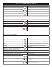
As you do Steps 4 and 5, watch for points where operation
deviates from normal. Refer to Troubleshooting Chart to
correct problem.
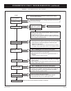
STEP 4: Check Safety Lockout Operation.
A. Turn gas supply off.
B. Set thermostat above room temperature to call for heat.
C. Watch for spark at pilot burner.
D. Time length of spark operation. Maximum spark time is 90
seconds.
E. Open manual gas cock and make sure no gas is flowing to
pilot or main burner.
F. Set thermostat below room temperature and wait one minute
before continuing.
STEP 5: Check Normal Operation.
A. Set thermostat above room temperature to call for heat.
B. Make sure pilot lights smoothly when gas reaches the pilot
burner.
C. Make sure main burner lights smoothly without flashback.
Make sure burner operates smoothly without floating or
lifting.
D. If gas line has been disturbed, complete gas leak test.
GAS LEAK TEST: Paint gas control gasket edges and
all pipe connections downstream of gas control, including
pilot tubing connections, with rich soap and water solution.
Bubbles indicate gas leaks. Tighten joints and screws or
replace component to stop gas leak.
E. Turn thermostat below room temperature. Make sure main
burner and pilot flames go out.
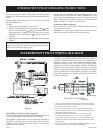
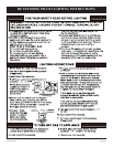
OPERATION
Module operation can be conveniently divided into two phases
for S8600H. The phases are trial for ignition and main burner
operation.
TRIAL FOR IGNITION
Pilot Ignition
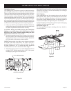
Following call for heat (system start on S8600H), the module
energizes the first main valve operator. The first main valve opens,
which allows gas to flow to the pilot burner. At the same time,
the electronic spark generator in the module produces a 13,000
volt spark pulse output (at 25 pf load). The voltage generates a
spark at the igniter-sensor that lights the pilot.
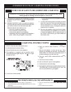
If the pilot does not light, or the pilot flame current is not at least
1.0 uA and steady, the module will not energize the second main
valve and the main burner will not light.
CALL SERVICEMAN
INTERMITTENT PILOT TROUBLESHOOTING