


www.desatech.com
117437-01B 9
This appliance may be vented through a manu-
factured chimney liner system if all are listed,
inspected and approved by local codes and/or
building authorities.
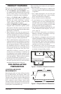
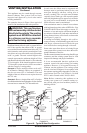
The examples shown in Figure 10 are typical of
most B-vent installations and code practices.
WARNING: This gas replace
and vent assembly must be vented
directly to the outside. The venting
system must NEVER be attached
to a chimney serving a separate
solid fuel burning appliance.
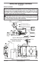
Example 1: Shows the minimum allowable system
height and lateral offset for a 60° or greater inclina-
tion. Code species that offsets at 60° or greater
are considered horizontal and must follow the 75%
rule for lateral to total vertical system height. Codes
also allows only one offset in the total system when
at 60° or greater. The total vertical height in this
example represents the minimum height of 8 feet
and therefore the allowable lateral is 6 feet when the
75% rule applies. If the lateral length must exceed
75% then the system must be sized in accordance
with the Category I venting tables.
Example 2: Shows multiple offsets each at 45°
of inclination. Multiple offsets are permitted if
they do not exceed 45° of inclination. The total
lengths of the two offsets are not required to meet
the 75% rule.
Example 3: Shows a single offset at 45° of inclina-
tion and therefore the lateral length at 10 feet of offset
does not have to meet the 75% allowable rule.
In each case the offsets must be supported and
restops must be positioned wherever the vent
must pass through a sub-oor, ceiling joist or
an attic overhang. The vent pipe must terminate
vertically into a listed type vent cap and extend a
sufcient height through an approved roof ash-
ing, roof jack or a roof thimble. At all points the
listed clearances must be maintained.
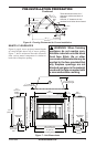
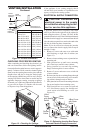
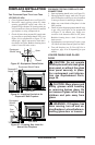
Vent terminations must be located in accordance
with height and proximity rules of NFPA No. 54 or
CAN/CSA B149. These rules apply to vents at 12"
diameter or less and require a minimum height in
accordance with the roof pitch and a minimum of
8 foot distance from a vertical wall or obstruction
(see Figure 11, page 10).
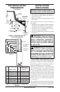
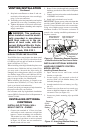
If venting horizontally through a side wall be-
comes necessary, a listed thimble approved for use
with B-type vent must be used. Check with your
local codes before venting through a side wall.
Some codes areas allow the use of existing B-type
vent systems if the system is at or above the recom-
mended diameter of the ue.
The ue connection must be made using listed B-type
connectors and the existing system must be code
inspected for damage and proper installation.
It is not recommended that this appliance be
common vented with and existing gas burning
appliance. However, if it becomes necessary to
common vent the appliance. The venting system
must be sized and congured in accordance with
the common venting guides Appendix G of the cur-
rent National Fuel Gas Code NFPA No. 54/ANSI
Z223.1 and in Canada with CAN/CSA B149.
Note: Before connecting this appliance to an
existing vent system or a common venting sys-
tem consult with your local architect planner, or
building ofcial.
Figure 10 - Typical B-Vent Conguration
Maintain
Listed
Clearance
Maintain
Listed
Clearance
12' Min.
12' Min.
45°
45
6'
8'
12' Min.
60
45
Position
Firestop
Position
Firestop
Position
Firestop
Listed
Vent Cap
Listed
Vent Cap
Listed
Vent Cap
Maintain
Listed
Clearance
Maintain
Listed
Clearance
Maintain
Listed
Clearance
Maintain
Listed
Clearance
Support Each
Lateral At
Least Every
6 Feet
Maintain
Listed
Clearance
10'
EXAMPLE 3EXAMPLE 2
EXAMPLE 1
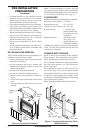
VENTING INSTALLATION
Continued