


www.desatech.com
117437-01B 5
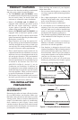
PRODUCT FEATURES
These are a few facts that can help you understand
and enjoy your vented decorative replace:
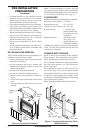
• The (V)CB36N(E) and (V)CB36P(E) series
of vented decorative replaces may be recessed
into an exterior chase, an interior ush wall
enclosure or a framed-in corner installation.
• Models (V)CB36N and (V)CB36P are
equipped with a millivolt gas control system
that does not require electricity to operate.
A piezo ignitor is provided to light the pilot
without using matches or lighters.
• Models (V)CB36N(E) and (V)CB36P(E) are
equipped with an electronic ignition system
that requires 120 VAC to operate. An electrode
ignitor automatically lights the pilot ame when
the replace is turned on.
• These replaces can accept any approved 4"
B-Type venting system and must be terminated
vertically through the roof using a listed type
vent cap only. See venting instructions starting
on page 8 for proper venting requirements.
• These vented replaces require indoor air for
combustion and must be installed in a room of
sufcient size to provide adequate fresh air for
safe and proper operation. The room intended
for installation must be of sufcient size to
meet the requirements for an unconned space
as dened in the National Fuel Gas Code,
ANSI Z223.1/NFPA 54, Section 5.3, Air for
Combustion and Ventilation. If sufcient air
for combustion is not available a makeup air kit
model AK4 may be required to provide outside
air to this appliance. Check your local codes as
to specic requirements for make up air.
• This replace may be installed in any room of
the house provided all local codes and these
installation instructions are followed.
PRE-INSTALLATION
PREPARATION
LOCATION AND SPACE
REqUIREMENTS
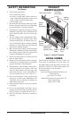
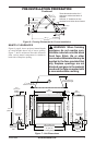
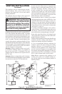
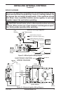
Determine the safest and most efcient location
for your DESA direct-vent replace. Make sure
that rafters and wall studs are not in the way of the
venting system. Choose a location where the heat
output is not affected by drafts, air conditioning
ducts, windows or doors. Figure 2 shows some
common locations. Be aware of all restrictions and
precautions before deciding the exact location for
your replace and termination cap.
When deciding the location of your replace,
follow these rules:
• Do not connect this replace to a chimney ue
servicing a separate solid fuel burning replace
or appliance.
• Do to high temperatures, do not locate this
replace in high traffic areas, windy or drafty
areas, or near furniture or draperies.
• Proper clearances must be maintained.
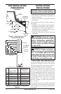
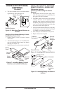
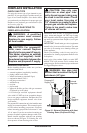
• If your replace is to be installed directly on
carpeting, vinyl, tile or any combustible mate-
rial other than wood, it must be installed on a
metal or wood panel extending the full width
and depth of the replace (see Figure 3).
• Only trim kits supplied by DESA shall be used
in the installation of this replace, see Acces-
sories, page 34.
• Do not install aftermarket vent dampers.
Manual or automatic vent dampers are not ap-
proved for use with this appliance.
• Your replace is designed to be used in zero
clearance installations. Wall or framing material
can be placed directly against any exterior sur-
face on the back, sides or top of your replace,
except when clearances are required from ue
vent pipe, see Clearances on page 6.
• If recessed into a wall, you can avoid extra
framing by positioning your replace against
an already existing framing member.
Through exterior wall
enclosed in a chase
Corner
Installation
Flush with a wall
Figure 2 - Common Fireplace Locations
25"
(63.5 cm)
36"
(91.4 cm)
36"
(91.4 cm)
Figure 3 - Fireplace Bottom Dimensions