


www.desatech.com
117437-01B22
INSPECTING BURNERS
Check pilot ame pattern and burner ame pat-
terns often.
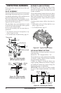
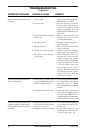
PILOT ASSEMBLY
The pilot assembly is factory preset for the proper
ame height. Alterations may have occurred dur-
ing shipping and handling. Call a qualied service
person to readjust the pilot if necessary.
The position and pattern of the pilot ames in rela-
tion to the sensing devices should be as shown in
Figures 38 and 39 respectively.
The pilot ame may need adjustment in order
for the thermocouple, thermopile and/or ignition
system to sense the pilot ame.
If your pilot assembly does not meet these re-
quirements:
• turn replace off (see To Turn Off Gas to Ap-
pliance, page 19 or 20)
• see sections under Troubleshooting, page 25
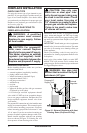
Thermocouple
Thermopile
1/4"
Pilot Burner
Piezo
Ignitor
Figure 38 - Pilot Assembly
(Millivolt Ignition System)
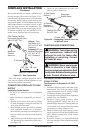
3/8" to 1/2"
Sensor
Rod
Pilot
Burner
Piezo
Ignitor
Figure 39 - Pilot Assembly
Electronic Ignition System)
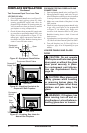
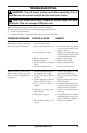
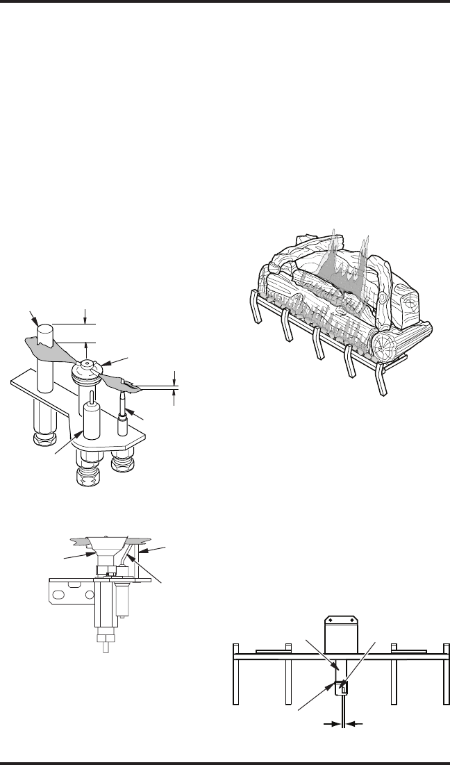
BURNER FLAME PATTERNS
Burner ames will be steady, not lifting or oat-
ing. Flame patterns will differ from unit to unit
and will vary depending on installation type and
weather conditions.
If vent conguration is installed incorrectly, ames
will lift or “ghost”. This can be dangerous. Inspect
ames after installation to ensure proper installa-
tion and performance. Figure 40 shows a typical
ame pattern.
If burner flame pattern differs from that de-
scribed:
• turn replace off (see To Turn Off Gas to Ap-
pliance, page 19 or 20)
• see Troubleshooting, page 25
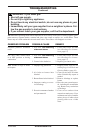
Figure 40 - Typical Flame Pattern
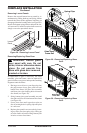
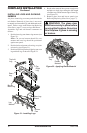
Figure 41 - Adjusting Air Setting
AIR ADjUSTMENT SETTING
The main burner air shutter opening is factory set
to the following:
Natural Gas - 1/8", Propane/LP Gas - 3/4"
The air shutter may require adjustment depending
on altitude, venting condition, burner operation
and general ame appearance.
If ames are lifting or sooting the shutter may
require opening. If ames are too blue or improp-
erly lighting the shutter may require closing. See
Figure 41 for proper air adjustment.
IMPORTANT: Do not reduce air shutter opening
any lower than designed minimum stop setting
of 1/8".
1/8" Minimum
Air Opening
Air
Shutter
Burner
Tube
Adjustment
Screw