


www.desatech.com
117437-01B 13
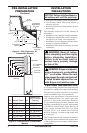
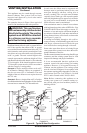
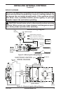
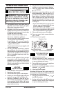
Figure 20 - Millivolt Ignition Wiring Diagram
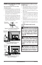
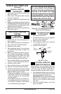
Figure 21 - Electronic Ignition Wiring Diagram
TH
TP
TH/TP
WHITE
RED
DO NOT
CONNECT
TO 120V
HIGH LIMIT
SWITCH
N
O
T
O
L
P
F
F
O
I
NC
Pilot
Burner
Incoming
Main Gas
Supply
Thermocouple
Wall Switch/Remote Receiver
Replace factory wiring with
105° C equivalent or higher rating
External wiring use only Class 2
thermostat wire 18 Ga. Red/White
Millivolt Wiring Diagram
WIRING DIAGRAMS
NOTICE: This appliance is equipped with a vent safety shutoff switch
which will shut down the appliance in case of a venting problem. Do
not bypass the vent safety shutoff switch. If the appliance should
shut down, have a qualied installer, service agency, or your gas
supplier inspect the vent before operating.
CAUTION: label all wires prior to disconnection when servicing
controls. Wiring errors can cause improper and dangerous opera-
tion. Verify proper operation after servicing.
EV2
EV1
High Limit
Switch
Gas Valve
Orange
Red
Red
Transformer
Ignition Control
Module
Black
Black
Ground
120 VAC
White
24 VAC
Blue
Blue
High Voltage
MV PV TH P/MV GND TR
Green
Ignition Module
ELECTRONIC IGNITION
WIRING DIAGRAM
Black
Pilot Burner
Ignitor
NC
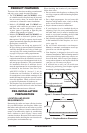
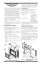
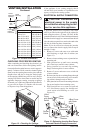
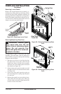
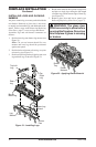
INSTALLING OPTIONAL CONTROLS
Continued