


www.desatech.com
117437-01B 7
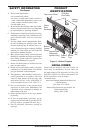
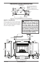
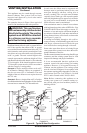
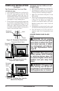
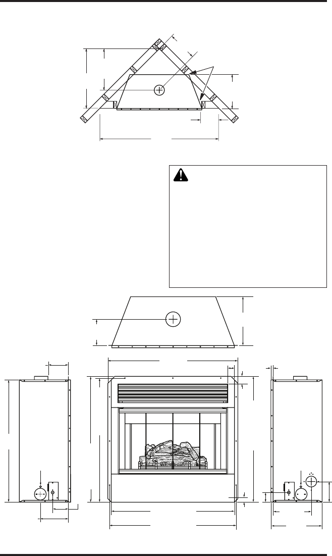
Figure 6 - Framing Clearances for Corner Installation
28
5
/
8
"
(72.7 cm)
21" (53.3 cm)
To Center of
Top Vent
14
3
/
4
"
(37.5 cm)
14
3
/
4
" (37.5 cm)
to Nailing
Flanges
56
3
/
4
"
(144 cm)
12
1
/
4
"
(31 cm)
to Opening
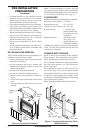
PRE-INSTALLATION PREPARATION
Continued
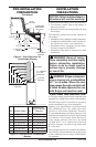
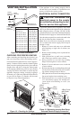
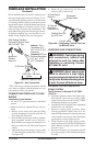
Figure 7 - Unit Dimensions
14
3
/
4
" (37.5 cm)
to Nailing Flanges
7
7
/
8
" (20 cm) to
Center of 4" B-Vent
5
7
/
8
"
(15 cm) to
Nailing
Flange
36
1
/
4
" (92.1 cm)
to Nailing Flange
36
1
/
4
" (92.1 cm)
Face Dimensions
1
1
/
2
" (3.8 cm)
2
1
/
2
" (6.4 cm)
6" (15.2 cm)
5/8"
(16 mm)
11
1
/
8
"
(28.3 cm)
Air Kit Location
1
1
/
4
"
(3.2 cm)
2"
(5.1 cm)
38"
(96.5 cm)
15
3
/
8
"
(39 cm)
36" (91.4 cm)
Face Dimensions
37" (94 cm)
to Nailing Flange
35
3
/
4
"
(90.8 cm)
4
1
/
2
" (11.4 cm) Electrical Inlet
36
3
/
4
" (93.4 cm)
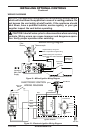
Wall Switch
Wireway
Wall Switch
Wireway
8" (20.3 cm)
Gas Supply
Inlet
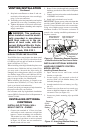
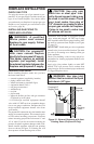
MANTEL CLEARANCES
Figure 8, page 8, shows projected mantel depths
at various heights above top of louver opening.
Figure 7 shows minimum allowable distances
from various mantel components in relation to
both sides of replace opening.
WARNING: When nishing
appliance do not overlap com-
bustible materials onto the black
front face. Brick, tile or other
noncombustible materials may be
applied to the face provided that
any replace openings are not
blocked and gaps in the material
used and the face are sealed with
a noncombustible caulking.
These dimensions allow for 1"
clearance at sides and back of
replace.
However, 0" clearance is also
permitted at all sides when framed.