


www.desatech.com
117437-01B 11
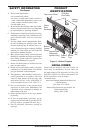
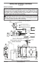
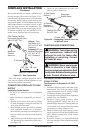
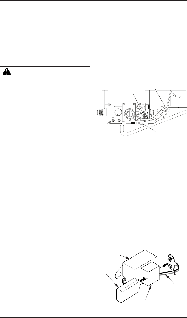
Remote Receiver
or Wall Switch to
Terminal Marked “TH”
Wire Harness From
High Limit Switch
Male Connector to
Remote Receiver
or Wall Switch
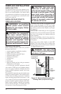
9. Strip back outer Romex to about 4" and con-
nect black, white and green wires accordingly
using 3 wire nut connectors.
10. Tuck tailing wires into junction box and replace
junction box cover using 2 remaining screws.
11. Tighten adjustment on universal strain bush-
ing to secure Romex sheathing and complete
supply connection.
WARNING: This appliance,
when installed must be electri-
cally grounded in accordance
with local code or in the ab-
sence of local code, with the
current National Electric Code,
ANSI/NFPA 70, or the Canadian
Electric Code, CSA C22.1.
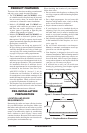
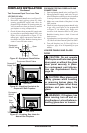
HIGH ALTITUDE INSTALLATION
Your DESA direct-vent replace has been tested
and approved in the USA for elevations from
0-2,000 feet (610 m) and in Canada at elevations
from 0-4,500 feet (1,372 m).
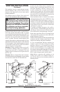
When installing a non-high altitude replace at an
elevation above 2,000 feet (610 m) (in the USA),
you may need to decrease the input rating by
changing the existing burner orice to a smaller
size. Reduce input 4% for each 1,000 feet (305 m)
above sea level. Check with your local gas com-
pany for proper orice size identication.
When installing this replace in Canada at an
elevation above 4,500 feet (1,372 m), Check with
local or provincial code authorities.
Consult your local gas company to help determine
the proper orice for your location.
For assistance with any high altitude installation
contact DESA’s Customer Service Department at
1-866-672-6040.
INSTALLING OPTIONAL
CONTROLS
INSTALLING OPTIONAL WALL
MOUNT SWITCH - GWMS2
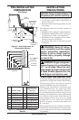
1. Connect one terminal of 15 foot wire from
wall switch to male connector on high limit
harness. Connect remaining wire terminal to
TH terminal on valve. Make sure that wire
terminals are in positions on unit as pictured
in Figure 14. If wires are not connected as
shown switch will not work.
VENTING INSTALLATION
Continued
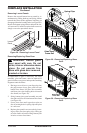
2. Route 15 foot wire through hole openings with
bushings provided on either side of replace
cabinet.
3. Connect one bare wire end to each of terminals
of GWMS2 wall switch.
4. Install wall switch and cover in wall.
IMPORTANT: Do not use any other wire than that
provided with GWMS2 wall switch kit. Do not
exceed 15 feet of distance from valve connection.
Using wire of higher gauge or turns or exceeding
minimum distance will increase resistance at
control valve causing unreliable performance of
replace controls.
Figure 14 - Connecting Remote Receiver
or Wall Switch to the Gas Control Valve
INSTALLING OPTIONAL WIRELESS
HAND-HELD REMOTE CONTROL
MODEL HRC100
Installing Remote Receiver
1. Open bottom louver and locate switch
bracket on right side.
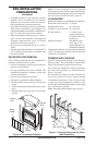
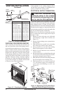
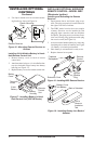
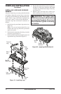
2. Locate battery clip mounted on back of
receiver. Slide a 9-volt alkaline battery (not
included) through clip.
3. Attach terminal wires to battery (see Fig-
ure 15).
4. Connect one wire from receiver to male con-
nector on high limit harness and one to “TH”
on control valve (see Figure 14).
5. Locate two plastic mounting clips provided
with kit.
9-Volt
Alkaline
Battery
Receiver
Terminal
Wires
Battery Clip
Figure 15 - Attaching Alkaline Battery to
Receiver