


36
WinterWarm Fireplace Insert or System
2000941
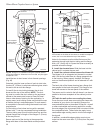
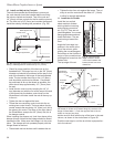
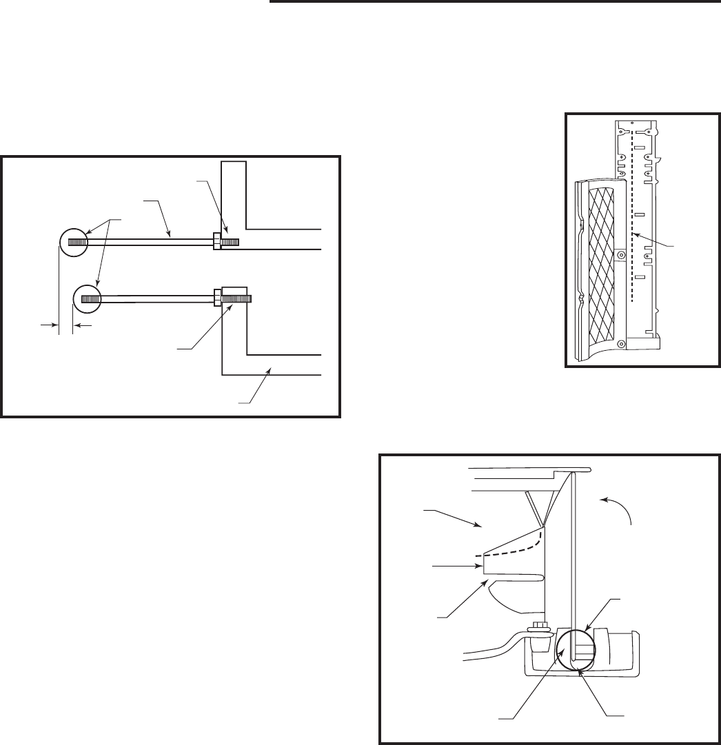
10. Install and Adjust the Controls.
The rods that operate the WinterWarm’s primary air,
fan, and damper should be installed before mounting
the column capitals and mantel. Two of the rods are
1/4” (6mm) and are controls for the fan and the primary
air. The third rod is 3/8” (9mm) and controls the damper.
Install the rods by following this procedure: (Fig. 56)
• Check for proper position of the hex nuts on the
threaded rods. The larger hex nut on the 3/8” (9mm)
diameter rod should be positioned all the way to the
end of the thread on the longer of the two threaded
ends. The two smaller hex nuts on the 1/4” (6mm)
rods should be positioned as follows: One should
be positioned as far up the thread as possible; the
other should stop approximately 1/2” (13mm) from
the end.
• Install the fan control rod by inserting the 1/4” (6
mm) diameter rod with the nut all the way at the end
of the thread into the bottom control lever on the
WinterWarm’s left side. Install the rod all the way up
to the nut.
• Tighten the hex nut against the lever.
• Thread the two remaining control rods into the re-
maining two control levers. The lever above the fan
control accepts the remaining 1/4” (6mm) rod; this is
the primary air control. The lever on the right side of
the WinterWarm accepts the 3/8” (9mm) rod; this is
the damper control.
When installing the damper rod, look from above at the
damper linkage. Note that the linkage should be flexed
towards the rear. Make sure the linkage is in this orien-
tation. The damper will not operated properly with the
linkage flexed to the front.
• Thread each rod into the lever until it reaches the nut.
• Tighten the two hex nuts against the levers. The pri-
mary air and fan controls will be offset 1/2” (13mm)
to allow for smooth adjustment.
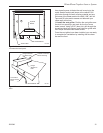
11. Install the Air Divider.
Install the two vertical
sheet metal air dividers
which guide the incoming
and outgoing convection
air. (Fig. 57) They are not
interchangeable: the curved
flange goes downward and
faces the firebox. The two
punchouts go toward the
front.
Angle the front edge into
position in the notch at the
top of the column, while
guiding the curved flange at
the bottom so that it slides in
on top of the curved horizon-
tal flange that is cast into the
firebox side.
The top edge of the air
FP1133
controls
7/2/01 djt
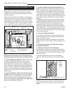
Blind-Tapped Hole
Control Lever
Brass
Knob
1/2” (13mm)
Through-Tapped Hole
L-Bracket
FP1133
Fig. 56 Adjsut the controls so the primary air control rod, on
the top, overhangs the fan control rod by 1/2” (13mm)
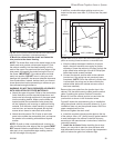
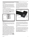
divider must be flush with the top of the boss in the cast
column, as shown in the circled area in Figure 58.
Push the rear edge in until the air divider is perpendicu-
lar to the column.
FP1135
air divider
top view
7/01
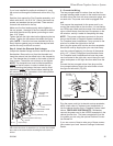
Cast Winter-
Warm Flange
Air Divider
Flange
2. Adjust
Bottom
Here
Boss
Notch
1. Seat Here
3. Push in
Here
FP1135
Fig. 58 1. Seat entire length of air divider in notch. 2. Adjust
the seated air divider so its bottom flange is just above cast
flange of WinterWarm. 3. Push the opposite side of the air
divider so it snaps into place.
FP1134
air divider
7/01
FP1134
Fig. 57 Seat the entire
length of the air divider
in the notch between the
bosses shown here as a
dotted line.
Air
Divider