


29
WinterWarm Fireplace Insert or System
2000941
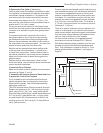
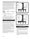
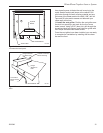
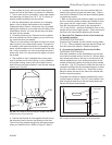
6. Move the cabinet into the chase and fasten the
trim panels to the chase framing.
NOTE: The chase floor must be the same height as the
hearth and must provide uninterrupted support. Push
the cabinet carefully into the chase opening until the
ends of the upper trim panel and the outer edges of the
side panels rest against the studs forming the front of
the chase. IMPORTANT: If the cabinet does not slide
easily into position, DO NOT force it; doing so could
damage the “standoffs” that ensure adequate clearance
from combustibles. Instead, double-check your framed
chase dimensions before proceeding to make sure you
have allowed enough clearance.
WARNING: DO NOT PACK REQUIRED AIR SPACES
WITH INSULATION OR OTHER MATERIALS.
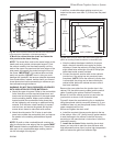
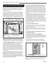
a. Attach the upper trim panel. Refer to the combustible
limits illustration and the required dimensions, and
locate one hole through each end of the upper panel
into the studding behind. Make sure the holes are
located outside the combustible limits where they
will be hidden by wall covering or additional facing
material. Drill the holes, check carefully for square
one last time, and secure the panels with drywall
screws driven home to make flush with surface.
b. Attach the side panels. Drill 2 holes in each side
panel, also outside the combustible limit, and secure
the panels to the studding with additional drywall
screws.
NOTE: Drywall or other combustible wall covering ap-
plied to overlap the outer edge of the trim panels MUST
NOT extend inside the combustible limits. These limits
also apply to any combustible edge molding used to
trim the raw edge of the drywall.
In addition, combustible edge molding must not pro-
trude into the room more than 2” (51mm) from the panel
surface.
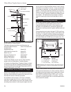
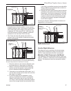
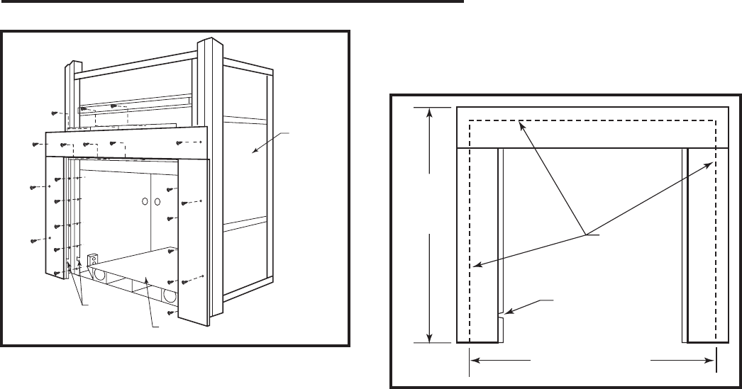
37³⁄₈"
(950mm)
40³⁄₈" (1026mm)
FP1122
upper trim panel ends
5/23/01 djt
Combustible
Limits
Notch for
Power Cord
FP1122
Fig. 44 Make sure you secure the ends of the upper trim
panels to studding located outside the combustible limits.
c. After the cabinet has been installed to its proper
depth, check all standoffs once again for proper
clearance. Screw the cabinet to the floor through the
eight drilled holes with eight of the #10 Phillips pan
head sheet metal screws provided.
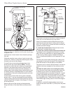
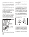
d. Connect the electric service cable to the cabinet’s
junction box if the wiring has not previously been
completed. (NOTE: Since the cabinet’s junction box
is removable, the wiring can be done outside the
cabinet either before the cabinet arrives or after it
has been installed.)
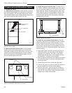
Remove the cover plate from the junction box in the
cabinet. Pull the electric service cable (and the switch
cable if installing the optional Cabinet Convection
Blower Kit) into the cabinet junction box and wire the
junction box as shown in the illustration below.
Figure 45 shows the required wiring for an installation
using the optional cabinet convection blower kit. If your
installation does not use the optional blower, ONLY the
upper receptacle will be live.
Secure and tighten the strain relief.
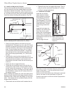
e. Install the required chimney anchor plate to the top
of the cabinet. Use a 1/8” (4mm) bead of gasket cement
to seal the flange to the cabinet. Install the chimney
according to the manufacturer’s instructions; follow the
instructions exactly.
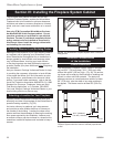
7. Install the air ducts.
Before installing the air duct
boxes, you may wish to paint the inner surfaces with
high temperature stove paint (or other high temperature
paint) to reduce the glare from reflected light.
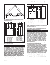
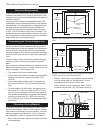
FP1121
front trim
Cabinet
Base
Notch
FP1121
Fig. 43 The trim panels fasten the cabinet to the chase fram-
ing and give the installation a finished appearance.