


28
WinterWarm Fireplace Insert or System
2000941
Prepare and Install WinterWarm Cabinet
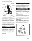
1. Unpack the carton.
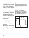
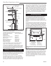
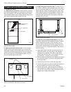
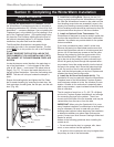
2. Install the flex connector. Install the flex connector
and attached flue flange to the underside of the cabinet
top using eight #10-1/2” hex head sheet metal screws.
The connector should point forward with the long axis of
the oval running from side to side. (Fig. 40)
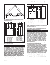
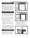
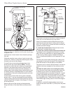
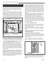
4. Install the spark protector strip. To install the 3” x
38” (76mm x 965mm) spark protector strip, first draw a
line on the hearth parallel and 2” (51mm) in front of the
chase opening. Center the spark protector strip in the
chase opening, with the outside edge on the line. Nail
or screw the strip down, painted side up, so that the
fastener heads are flush with the surface of the spark
protector strip. (Fig. 42)
FP1118
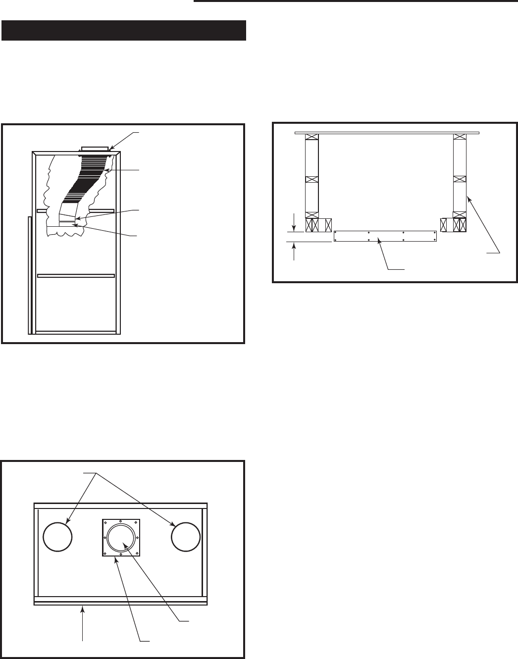
Chimney connector
5/23/01 djt
Anchor Plate
Flexible Chimney
Connector
20° Offset Piece
Flue Collar
FP1118
Fig. 40 Proper position of the chimney connector, offset slip
piece and anchor plate.
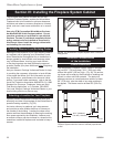
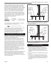
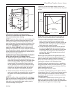
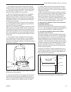
3. Mark and drill the anchor plate. Fit the chimney
system anchor plate appropriate to your chosen pre-
fabricated chimney over the flue outlet at the top of the
cabinet and mark the attaching hole centers; remove
the anchor plate and drill the fastener holes. (Fig. 41)
Do not install the plate at this time.
FP1119
anchor plate
5/23/01 djt
Convection
Air Outlets
Front
Anchor Plate
Flue Opening
FP1119
Fig. 41 The anchor plate mounts on top of the cabinet and
secures the chimney to the chimney connector.
2" (50mm)
FP1120
Spark protector
5/23/01 djt
Chase
Spark Protector
FP1120
Fig. 42 Install spark protector.
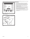
5. Attach the trim pieces to the cabinet. (Fig. 43)
The parts supplied for this procedure include 16 sheet
metal screws and one each of the following: an up-
per trim panel, a left trim panel and a right trim panel.
You will also need an electric drill equipped with a 1/8”
(3mm) bit and a 5/16” (8mm) head driver, and a felt tip
pen for marking.
a. Align the 5 holes in the left trim panel with the cor-
responding holes in the left edge of the fireplace
opening on the cabinet. The notch in the flange
should align with the notch in the cabinet front, ap-
proximately 4” (102mm) from the bottom.
b. With the electric drill and the hex head driver, secure
the trim panel using 5 of the hex head sheet metal
screws provided.
c. Repeat this procedure to install the right panel.
d. Position the upper trim panel on top of the side pan-
els and centered on the face of the cabinet.
e. With the felt tip pen, mark through the 3 holes on
each flange of the upper trim panel on the cabinet,
and drill 1/8” (3mm) holes. Secure the panel to the
cabinet with 6 sheet metal screws.