


23
WinterWarm Fireplace Insert or System
2000941
FP1089
WinterWArm
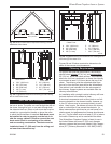
trim sizes
3/28/01 djt
66" (1683mm)
66" (1683mm)
27"
(686mm)
27"
(686mm)
39¹⁄₂"
(1003mm)
93¹⁄₂" (237cm)
FP1091
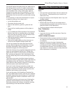
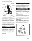
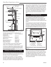
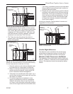
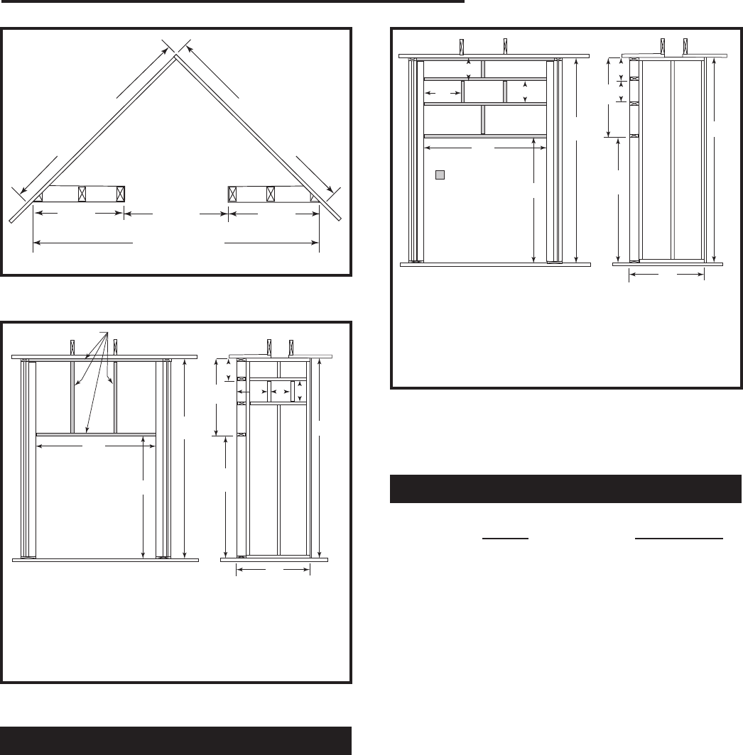
Fig. 22 Minimum dimensions required for framing a corner
installation of the chase.
I
B
D
E
C
B
A
C
FP1093
WinterWarm
Front vent framing
dimensions
4/2/01 djt
E
G
F F
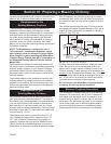
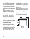
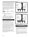
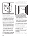
A 39¹⁄₂” (1003 mm) E 12” (305 mm)
B 62” (1575 mm) F 9³⁄₄” (248 mm)
C 89” (2260 mm) G 12¹⁄₈” (308 mm)
D 28” (711 mm) I 28
¹⁄₂” (724 mm)
Chase Front
Chase Side
FP1093
Fig. 29 Suggested framing and dimensions for venting the air
ducts through the chase front.
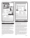
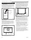
Duct and Vent Placement
The WinterWarm offers great flexibility in positioning
the hot air ducts. The ducts can vent through the side of
the chase, through its front, or one each through both
the side and the front. Either or both ducts also may be
vented into a room behind, beside or above the room
in which the WinterWarm is installed. Both ducts must
be installed in order to properly vent the hot air in-
side the energy cabinet. Failure to connect the vent
ducts could result in overheating of the cabinet
and surrounding construction. The ducts must be
installed at least 12” (305 mm) from the ceiling and
no lower than the cabinet top.
Figures 28 and 29 show construction dimensions for
some of the common duct placements.
Chimney Requirements
For proper draft and best performance, the chimney
should extend at least 15’ (4.6 m), and not more than
35’ (10.6 m), above the hearth surface. If the chimney
above the roof line is enclosed in a chase, the chimney
must extend at least 3’ (914 mm) above the top of the
chase. The chimney must be supported either from
the roof or from the floor joists above the WinterWarm.
The cabinet is not intended to be the sole support of
the chimney. Support systems are available from the
chimney manufacturer.
An installation with a straight, vertical chimney will have
the best draft and is the easiest to clean.
If structural components such as floor joists or roof raf
-
ters are obstacles to the chosen location, however, up
to four 30° elbows may be connected directly to each
other. Used in pairs, the elbows will return the chimney
pipe to vertical after it has passed the obstacle. (In
some instances floor joists can be cut and boxed in for
reinfor
cement, but engineered roof trusses should never
be cut.) The first offset must be at least 8’ (2.5 m) above
the hearth. Elbows may not be used within the chase.
The WinterWarm Fireplace System is listed for use in
the United States with seven 8” (203 mm) diameter
chimney systems that have been listed to High Temper-
ature (H.T.) Chimney Standard UL-103-1985 (2100°F).
I
B
D
E
F G
H
C
B
A
C
FP1092
WinterWarm
Side vent framing
dimensions
4/2/01 djt
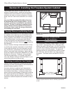
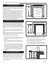
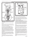
2” x 4” or Smaller
FP1092
Chase Front
Chase Side
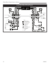
A 39¹⁄₂” (1003 mm) F 9³⁄₄” (248 mm)
B 62” (1575 mm) G 12¹⁄₈” (308 mm)
C 89” (2260 mm) H 9³⁄₄” (248 mm)
D 28” (711 mm) I 28
¹⁄₂” (724 mm)
E 12” (305 mm)
Fig. 28 Suggested dimensions and framing for side-venting
the air ducts of the chase.