


39
of dishwasher detergent and water is recommended for
cleaning both sides of the coil, followed by a thorough water
rinse. Clean coil with a stiff brush, vacuum cleaner, or com-
pressed air. Use a fin comb of the correct tooth spacing when
straightening mashed or bent coil fins.
Condenser Cleaning — Water-cooled condensers may
require cleaning of scale (water deposits) due to improperly
maintained closed-loop water systems. Sludge build-up may
need to be cleaned in an open water tower system due to
induced contaminants.
Local water conditions may cause excessive fouling or
pitting of tubes. Condenser tubes should therefore be cleaned at
least once a year, or more often if the water is contaminated.
Proper water treatment can minimize tube fouling and
pitting. If such conditions are anticipated, water treatment
analysis is recommended. Refer to the Carrier System Design
Manual, Part 5, for general water conditioning information.
Clean condensers with an inhibited hydrochloric acid
solution. The acid can stain hands and clothing, damage
concrete, and, without inhibitor, damage steel. Cover sur-
roundings to guard against splashing. Vapors from vent pipe
are not harmful, but take care to prevent liquid from being
carried over by the gases.
Warm solution acts faster, but cold solution is just as effec-
tive if applied for a longer period.
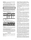
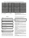
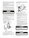
GRAVITY FLOW METHOD — Do not add solution faster
than vent can exhaust the generated gases.
When condenser is full, allow solution to remain overnight,
then drain condenser and flush with clean water. Follow acid
manufacturer’s instructions. See Fig. 32.
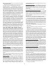
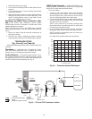
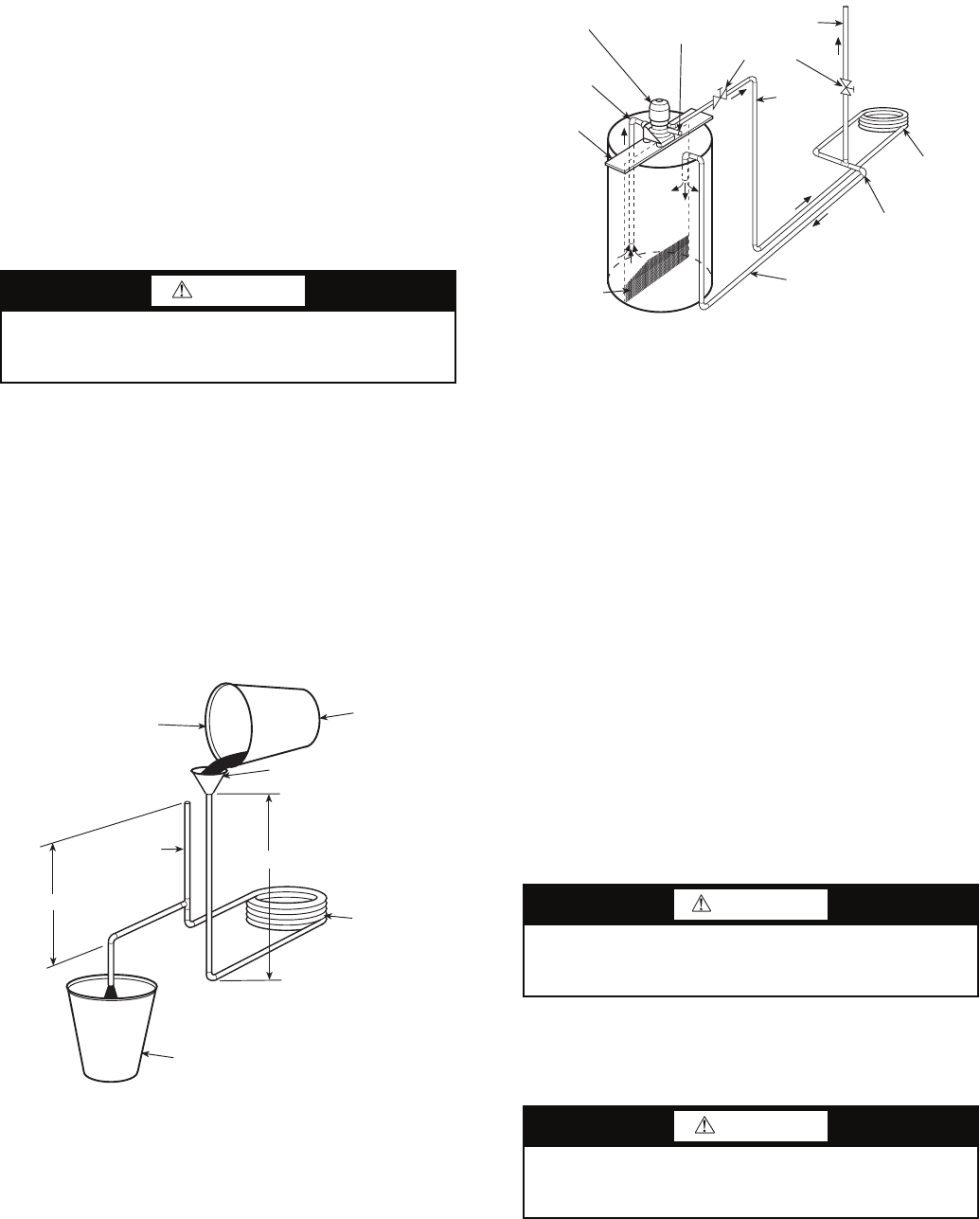
FORCED CIRCULATION METHOD — Fully open vent
pipe when filling condenser. The vent may be closed when
condenser is full and pump is operating. See Fig. 33.
Regulate flow to condenser with a supply line valve. If
pump is a nonoverloading type, the valve may be fully closed
while pump is running.
For average scale deposit, allow solution to remain in
condenser overnight. For heavy scale deposit, allow 24 hours.
Drain condenser and flush with clean water. Follow acid manu-
facturer’s instructions.
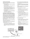
Checking System Charge — Units are shipped with
full operating charge. If recharging is necessary:
1. Insert thermometer bulb in insulating rubber sleeve on
liquid line near filter drier. Use a digital thermometer for
all temperature measurements. DO NOT use a mercury
or dial-type thermometer.
2. Connect pressure gage to discharge line near compressor.
3. After unit conditions have stabilized, read head pressure
on discharge line gage.
NOTE: Operate unit a minimum of 15 minutes before
checking charge.
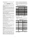
4. From standard field-supplied Pressure-Temperature
chart for R-410A, find equivalent saturated condens-
ing temperature.
5. Read liquid line temperature on thermometer; then
subtract from saturated condensing temperature. The dif-
ference equals subcooling temperature.
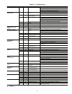
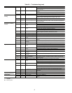
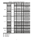
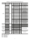
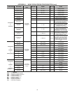
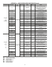
6. Compare the subcooling temperature with the normal
temperature listed in Tables 16-22. If the measured liquid
line temperature does not agree with the required liquid
line temperature, ADD refrigerant to raise the tempera-
ture or REMOVE refrigerant (using standard practices) to
lower the temperature (allow a tolerance of ± 3° F).
Refrigerant Charging
NOTE: Do not vent or depressurize unit refrigerant to
atmosphere. Remove and recover refrigerant following
accepted practices.
Air Coil Fan Motor Removal
Disconnect motor power wires from motor terminals before
motor is removed from unit.
CAUTION
Follow all safety codes. Wear safety glasses and rubber
gloves when using inhibited hydrochloric acid solution.
Observe and follow acid manufacturer’s instructions.
WARNING
To prevent personal injury, wear safety glasses and gloves
when handling refrigerant. Do not overcharge system —
this can cause compressor flooding.
CAUTION
Before attempting to remove fan motors or motor mounts,
place a piece of plywood over evaporator coils to prevent
coil damage.
Fig. 32 — Gravity Flow Method
FILL CONDENSER WITH
CLEANING SOLUTION. DO
NOT ADD SOLUTION
MORE RAPIDLY THAN
VENT CAN EXHAUST
GASES CAUSED BY
CHEMICAL ACTION.
PAIL
FUNNEL
CONDENSER
PAIL
3’ TO 4’
VENT
PIPE
5’ APPROX
1”
PIPE
SUCTION
PUMP
SUPPORT
TANK
FINE MESH
SCREEN
RETURN
GAS VENT
PUMP
PRIMING
CONN.
GLOBE
VALVES
SUPPLY
1” PIPE
CONDENSER
REMOVE WATER
REGULATING VALVE
Fig. 33 — Forced Circulation Method