


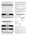

14
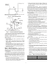
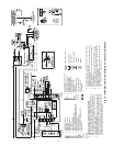
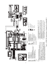
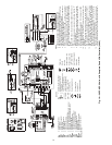
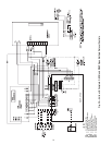
Fig. 16 — 50PCH,PCV Units with Complete C and LON Controller (460 V)
Complete C
a50-8493
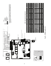
LEGEND
AL — Alarm Relay Contacts
BM — Blower Motor
BMC — Blower Motor Capacitor
BR — Blower Relay
CAP — Compressor Capacitor
CB — Circuit Breaker
CC — Compressor Contactor
CO — Sensor, Condensate Overflow
FP1 — Sensor, Low Temperature Protection, Water Coil
FP2 — Sensor, Low Temperature Protection, Air Coil
HP — High-Pressure Switch
HPWS — High-Pressure Water Switch
JW1 — Clippable Field Selection Jumper
LOC — Loss of Charge Pressure Switch
LON — Local Operating Network
MV — Motorized Valve
MVES — Motorized Valve End Switch
NEC — National Electrical Code
*Optional Wiring.
P1 — Field Wiring Terminal Block
RVS — Reversing Valve Solenoid
TRANS — Transformer
TXV — Thermostatic Expansion Valve
Field Line Voltage Wiring
Field Low Voltage Wiring
Printed Circuit Trace
Optional Wiring
Relay/Contactor Coil
Condensate Pan
Solenoid Coil
Temperature Switch
Thermistor
Ground
Wire Nut
Relay Contacts - N.C.
Relay Contacts - N.O.
Low Pressure Switch
High Pressure Switch
Splice Cap
Circuit Breaker
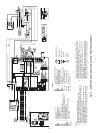
NOTES:
1. Compressor and blower motor thermally protected internally.
2. All wiring to the unit must comply with NEC and local codes.
3. Transformer is wired to 460 v BLK/RED lead for 460-3-60 units. Trans-
former is energy limiting or may have circuit breaker.
4. FP1 thermistor provides low temperature protection for water. When
using antifreeze solutions, cut JW3 jumper.
5. Refer to microprocessor control, LON, or thermostat installation
instructions for wiring to the unit. Wire “N01” from LON to “Y1” Com-
plete C when a motorized valve is not used. Low voltage wiring must
be Class 1 and voltage rating equal to or greater than unit supply
voltage.
6. Factory cut JW1 jumper. Dry contact will be available between AL1 and
AL2.
7. Transformer secondary ground via green wire with yellow strip from “C”
terminal to control box.
8. Fan motors are factory wired for medium speed. For high or low speed,
remove BLU wire from fan motor speed tap “M” and connect to “H” for
high speed or “L” for low speed.
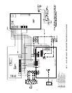
9. For low speed, remove BLK wire from BR “6” and replace with RED.
Connect BLK and BRN wires together.
10. Optional LON wires. Only connect if LON connection is desired at the
wall sensor.
11. For blower motors with leads. For medium or low speed, disconnect
BLK wire from BR “6”. Connect BLK and ORG/PUR wire together.
Connect RED for low or BLU for medium to BR “6”.
12. Blower motor factory wired to medium speed. For low speed remove
BLU wire from medium tap and connect to low speed tap. For high
speed, remove BLU wire from exisiting speed tap and remove BRN
jumper wire from high speed tap. Connect BLU wire to high speed tap.
Tape off unconnected end of BRN jumper.
13. The 460-v units using an internal secondary pump will require a neu-
tral wire from the supply side in order to feed the accessory with 265-v.