


3
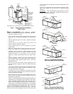
or an equivalent protective covering. Cap open ends of pipes
stored on the jobsite. This precaution is especially important in
areas where painting, plastering, or spraying of fireproof mate-
rial, etc. is not yet complete. Foreign material that accumulates
within the units can prevent proper start-up and necessitate
costly clean-up operations.
Before installing any of the system components, be sure to
examine each pipe, fitting, and valve, and remove any dirt or
foreign material found in or on these components.
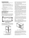
INSPECT UNIT — To prepare the unit for installation, com-
plete the procedures listed below:
1. Compare the electrical data on the unit nameplate with
ordering and shipping information to verify that the
correct unit has been shipped.
2. Verify that the unit is the correct model for the entering
water temperature of the job.
3. Do not remove the packaging until the unit is ready for
installation.
4. Verify that the refrigerant tubing is free of kinks or dents,
and that it does not touch other unit components.
5. Inspect all electrical connections. Be sure connections are
clean and tight at the terminals.
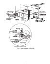
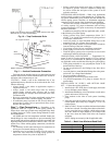
6. Loosen compressor bolts until the compressor rides freely
on springs. Remove shipping restraints.
7. Remove the four
1
/
4
in. shipping bolts from compressor
support plate (two bolts on each side) to maximize vibra-
tion and sound alternation.
8. Remove any blower support cardboard from inlet of the
blower.
9. Locate and verify any accessory kit located in compressor
section.
10. Remove any access panel screws that may be difficult to
remove once unit is installed.
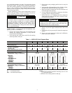
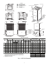
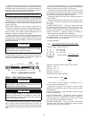
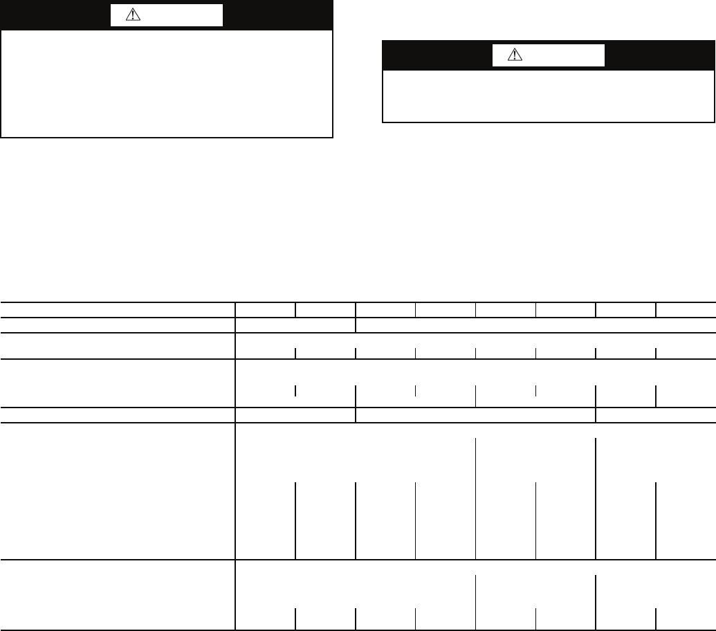
Table 1 — 50PCH,PCV Unit Physical Data
LEGEND *Front is located at control box end.
NOTES:
1. All units have grommet compressor mountings, and
1
/
2
-in. and
3
/
4
-in. electrical knockouts.
2. Maximum water working pressure is 500 psig.
CAUTION
DO NOT store or install units in corrosive environments or
in locations subject to temperature or humidity extremes
(e.g., attics, garages, rooftops, etc.). Corrosive conditions
and high temperature or humidity can significantly reduce
performance, reliability, and service life. Always move
units in an upright position. Tilting units on their sides may
cause equipment damage.
CAUTION
Failure to remove shipping brackets from spring-mounted
compressors will cause excessive noise and could cause
component failure due to added vibration.
50PCH,PCV UNIT 015 018 024 030 036 042 048 060
COMPRESSOR (1 each) Rotary Scroll
REFRIGERANT TYPE R-410A
Factory Charge (oz) 32 43 43 47 50 70 74 82
FAN MOTOR AND BLOWER
Fan Motor Type/Speeds PSC/3
Fan Motor (hp)
1
/
6
1
/
6
1
/
4
3
/
4
1
/
2
3
/
4
3
/
4
1
Blower Wheel Size (Dia x W) (in.) 8 x 7 9 x 7 9 x 8 10 x 10 11 x 10
WATER CONNECTION SIZE IPT (in.)
1
/
2
3
/
4
1
HORIZONTAL
Air Coil Dimensions (H x W)(in.) 16 x 22 20 x 25 20 x 35
Standard Filter - (Qty) 1 in. Throwaway (1) 16 x 25 (1) 20 x 28 or
(2) 20 x 14
(1) 20 x 24,
(1) 20 x 14
Weight (lb)
Operating 153 158 189 197 203 218 263 303
Packaged 158 163 194 202 209 224 270 310
Corner Weight (lb)*
Left-Front 53 55 62 67 75 81 98 103
Right-Front 36 37 40 41 47 50 60 64
Left-Back 34 35 39 40 44 48 58 61
Right-Back 30 31 33 34 37 39 47 75
VERTICAL
Air Coil Dimensions (H x W)(in.) 20 x 17.25 24 x 17.75 24 x 28.25
Standard Filter - (Qty) 1 in. Throwaway (1) 20 x 20 (1) 24 x 24 (1) 14 x 28, (1) 18 x 24
Weight (lb)
Operating 153 158 189 197 203 218 263 278
Packaged 158 163 194 202 209 224 270 285
IPT — Internal Pipe Thread
PSC — Permanent Split Capacitor