


24
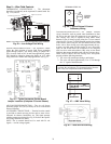
Wiring a Supply Air Temperature (SAT) Sensor
— The
SAT sensor is required for reheat applications.
If the cable used to wire the SAT sensor to the controller
will be less than 100 ft, an unshielded 22 AWG (American
Wire Gage) cable should be used. If the cable will be greater
than 100 ft, a shield 22 AWG cable should be used. The cable
should have a maximum length of 500 ft.
To wire the SAT sensor to the controller:
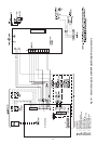
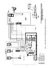
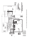
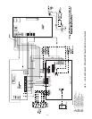
1. Wire the sensor to the controller. See Fig. 18-22.
2. Verify that the Enable SAT jumper is on.
3. Verify that the Enable SAT and Remote jumper is in the
left position.
Wiring an Indoor Air Quality (IAQ) Sensor
— An IAQ
sensor monitors CO
2
levels. The WSHP Open controller uses
this information to adjust the outside-air dampers to provide
proper ventilation. An IAQ sensor can be wall-mounted or
mounted in a return air duct. (Duct installation requires an aspi-
rator box assembly.)
The sensor has a range of 0 to 2000 ppm and a linear 4 to
20 mA output. This is converted to 1 to 5 vdc by a 250-ohm,
1
/
4
watt, 2% tolerance resistor connected across the zone con-
troller’s IAQ input terminals.
NOTE: Do not use a relative humidity sensor and CO
2
sensor
on the same zone controller if both sensors are powered off the
board. If sensors are externally powered, both sensors may be
used on the same zone controller.
If the cable used to wire the IAQ sensor to the controller
will be less than 100 ft, an unshielded 22 AWG (American
Wire Gage) cable should be used. If the cable will be greater
than 100 ft, a shield 22 AWG cable should be used. The cable
should have a maximum length of 500 ft.
To wire the IAQ sensor to the controller:
1. Wire the sensor to the controller. See Fig. 18-22.
2. Install a field-supplied 250-ohm,
1
/
4
watt, 2% tolerance
resistor across the controller’s RH/IAQ and Gnd
terminals.
3. Verify the the RH/IAQ jumper is set to 0 to 5-vdc.
Wiring a Relative Humidity (RH) Sensor
— The RH sensor
is used for zone humidity control (dehumidification) if the
WSHP unit has a dehumidification device. If not, the sensor
only monitors humidity.
NOTE: Do not use a relative humidity sensor and CO
2
sensor
on the same zone controller if both sensors are powered off the
board. If sensors are externally powered, both sensors may be
used on the same zone controller.
If the cable used to wire the RH sensor to the controller will
be less than 100 ft, an unshielded 22 AWG (American Wire
Gage) cable should be used. If the cable will be greater than
100 ft, a shield 22 AWG cable should be used. The cable
should have a maximum length of 500 ft.
To wire the RH sensor to the controller:
1. Strip the outer jacket from the cable for at least 4 inches.
2. Strip
1
/
4
in. of insulation from each wire.
3. Wire the sensor to the controller.
PRE-START-UP
System Checkout —
When the installation is complete,
follow the system checkout procedure outlined below before
starting up the system. Be sure:
1. Voltage is within the utilization range specifications of the
unit compressor and fan motor and voltage is balanced
for 3 phase units.
2. Fuses, breakers and wire are correct size.
3. Low voltage wiring is complete.
4. Piping and system flushing is complete.
5. Air is purged from closed loop system.
6. System is balanced as required. Monitor if necessary.
7. Isolation valves are open.
8. Water control valves or loop pumps are wired.
9. Condensate line is open and correctly pitched.
10. Transformer switched to lower voltage tap if necessary.
11. Blower rotates freely — shipping support is removed.
12. Blower speed is on correct setting.
13. Air filter is clean and in position.
14. Service/access panels are in place.
15. Return-air temperature is between 40 to 80 F heating and
50 to 110 F cooling.
16. Air coil is clean.
17. Control field-selected settings are correct.
AIR COIL — To obtain maximum performance, clean the air
coil before starting the unit. A ten percent solution of dish-
washer detergent and water is recommended for both sides of
the coil. Rinse thoroughly with water.
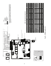
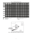
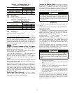
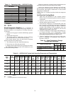
PSC (Permanent Split Capacitor) Blower
Speed Selection — All water source heat pumps are
factory set to deliver rated airflow at nominal static (0.15 in.
wg) on medium speed. Where higher static is needed, high
speed can be utilized (0.4 to 0.5 in. wg). Low speed will
deliver approximately 85% of rated airflow (0.10 in. wg). The
PSC blower fan speed can be changed on all units by swapping
wires connected to the relay contacts that control the fan. See
Fig. 30.
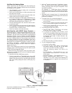
The PSC blower fan speed can be changed by moving the blue
wire on the fan motor terminal block to the desired speed as
shown in Fig. 30. The 50PC units are designed to deliver rated
airflow at nominal static (0.15 in. wg) on medium speed
(factory setting) and rated airflow at a higher static (0.4 to
0.5 in. wg) on high speed for applications where higher static is
required. Low speed will deliver approximately 85% of rated
airflow at 0.10 in. wg. An optional ‘high static’ blower is avail-
able by using the special option code in the model
nomenclature.
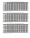
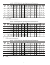
NOTE: Blower performance is shown in Tables 8-11.
CONNECT THE BLUE WIRE TO:
FAN MOTOR
MEDIUM FACTORY SETTING
H FOR HIGH SPEED FAN
M FOR MEDIUM SPEED FAN
L FOR LOW SPEED FAN
H
M
L
BLU
Fig. 30 — Blower Speed Selection