


23
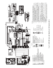
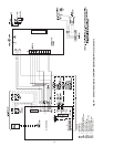
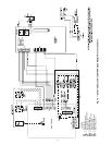
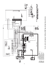
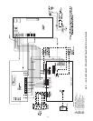
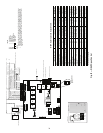
WSHP OPEN WIRING — The WSHP Open controller will
be factory wired to the Complete C or Deluxe D control board,
however, the system wiring will need to be completed utilizing
WSHP Open controller wiring diagrams and the Third Party
Integration (TPI) Guide. Factory installation includes harness,
LWT (leaving water temperature), supply air, and condensate
sensor.
Wiring Sensors to Inputs
— Sensors can be wired to the
WSHP Open controller’s inputs. See Table 4.
All field control wiring that connects to the WSHP Open con-
troller must be routed through the raceway built into the corner
post. The raceway provides the UL required clearance between
high and low-voltage wiring.
1. Pass control wires through the hole provided in the corner
post.
2. Feed the wires through the raceway to the WSHP Open
controller.
3. Connect the wires to the removable Phoenix connectors.
4. Reconnect the connectors to the board.
Field-Supplied Sensor Hardware
— The WSHP Open con-
troller is configurable with the following field-supplied sen-
sors. See Table 4.
Table 4 — Field-Supplied Sensors for
WSHP Open Controller
NOTE: BACview
6
Handheld or Virtual BACview can be used as the
user interface.
For specific details about sensors, refer to the literature sup-
plied with the sensor.
Wiring a SPT Sensor
— A WSHP Open controller is connect-
ed to a wall-mounted space temperature (SPT) sensor to moni-
tor room temperature using a Molex plug.
The WSHP Open system offers the following SPT sensors.
See Table 5.
Wire SPT sensors to the WSHP Open controller’s Rnet port.
An Rnetbus can consist of any of the following combinations
of devices wired in a daisy-chain configuration:
• 1 SPT Plus, SPT Pro, or SPT Pro Plus sensors
• 1 to 4 SPT Standard sensors
• 1 to 4 SPT Standard sensors and 1 SPT Plus, SPT Pro, or
SPT Pro Plus sensor
• Any of the above combinations, plus up to 2 BACvie w
6
Handheld but no more than 6 total devices
NOTE: If the Rnetbus has multiple SPT Standard sensors, each
sensor must be given a unique address on the Rnetbus. See the
Carrier Open Sensor Installation Guide.
Use the specified type of wire and cable for maximum signal
integrity. See Table 6.
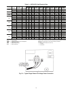
Table 5 — SPT Sensors
*The SPT Pro Plus fan speed adjustment has no effect in this
application.
Table 6 — Rnet Wiring Specifications
LEGEND
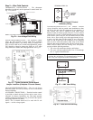
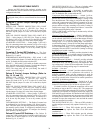
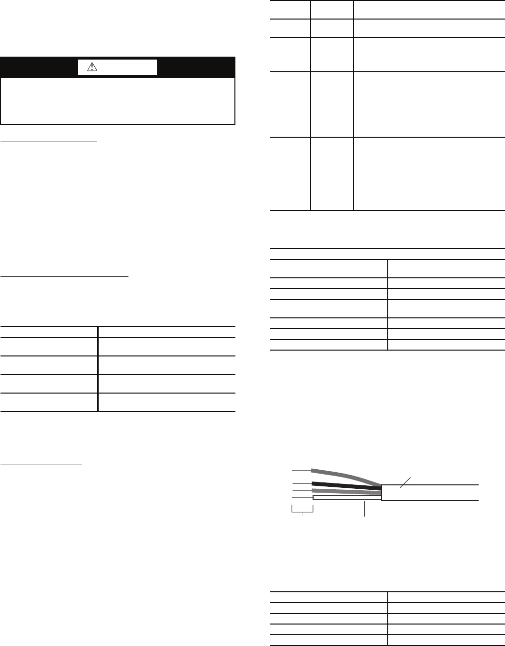
To wire the SPT sensor to the controller:
1. Partially cut , then bend and pull off the outer jacket of
the Rnet cable(s), being careful not to nick the inner
insulation.
2. Strip about
1
/
4
in. of the inner insulation from each wire.
See Fig. 29.
3. Wire each terminal on the sensor to the same terminal on
the controller. See Fig. 18-22. Table 7 shows the recom-
mended Rnet wiring scheme.
Table 7 — Rnet Wiring
NOTE: The wire should be connected to the terminal shown.
WARNING
Disconnect all power to the unit before performing mainte-
nance or service. Unit may automatically start if power is
not disconnected. Failure to follow this warning could
cause personal injury, death, and/or equipment damage.
SENSOR NOTES
Space Temperature Sensor
(SPT)
Field Installed (Must be used with
WSHP Open controller.)
Outdoor Air
Temperature Sensor
Network Sensor
Indoor Air Quality Sensor
(Separate Sensor)
Required only for demand
control ventilation.
Space Relative Humidity
Sensor
Separate Sensor
SENSOR
PART
NUMBER
FEATURES
SPT
Standard
SPS
• Local access port
• No operator control
SPT Plus SPPL
• Slide potentiometer to adjust set point
• Manual on button to override schedule
• LED to show occupied status
• Local access port
SPT Pro SPP
• LCD display
• Manual on button to override schedule
• Warmer and cooler buttons to adjust set
point
• Info button to cycle through zone and
outside air temperatures, set points, and
local override time
• Local access port
SPT Pro
Plus
SPPF
• LCD display
• Manual on button to override schedule
• Warmer and cooler buttons to adjust set
point
• Info button to cycle through zone and
outside air temperatures, set points, and
local override time
• Local access port
• Fan speed*
RNET WIRING SPECIFICATIONS
Description
4 conductor, unshielded, CMP,
plenum rated cable
Conductor 18 AWG
Maximum Length 500 ft
Recommended Coloring
Jacket: white
Wiring: black, white, green, red
UL Temperature 32 to 167 F
Voltage 300-vac, power limited
Listing UL: NEC CL2P, or better
AWG — American Wire Gage
CMP — Communications Plenum Cable
NEC — National Electrical Code
UL — Underwriters Laboratories
WIRE TERMINAL
Red +12-v
Black .Rnet
White Rnet+
Green Gnd
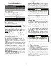
Fig. 29 — Rnet Cable Wire
OUTER JACKET
INNER INSULATION
.25 IN.
a50-8443
–