


27
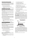
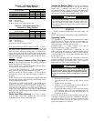
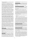
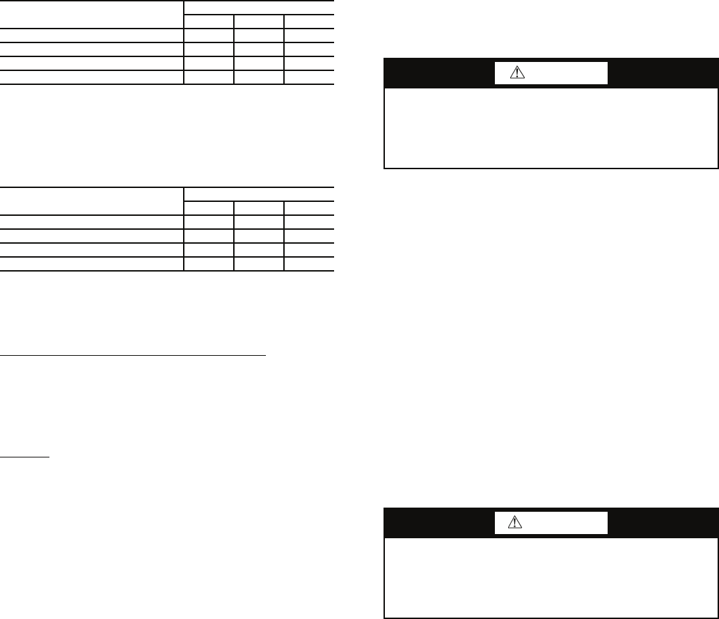
Table 12 — DIP Switch Block S2 —
Accessory 1 Relay Options
LEGEND
NOTE: All other DIP switch combinations are invalid.
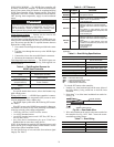
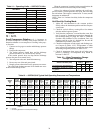
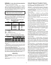
Table 13 — DIP Switch Block S2 —
Accessory 2 Relay Options
LEGEND
NOTE: All other switch combinations are invalid.
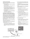
Auto Dehumidification Mode or High Fan Mode — Switch 7
provides selection of auto dehumidification fan mode or high
fan mode. In auto dehumidification fan mode the fan speed
relay will remain off during cooling stage 2 if terminal H is
active. In high fan mode, the fan enable and fan speed relays
will turn on when terminal H is active. Set the switch to ON for
auto dehumidification fan mode or to OFF for high fan mode.
Switch 8
— Not used.
Deluxe D Control Accessory Relay Configura-
tions — The following accessory relay settings are applica-
ble for both Deluxe D controls only:
CYCLE WITH FAN — In this configuration, the relay will be
ON any time the Fan Enable relay is on.
CYCLE WITH COMPRESSOR — In this configuration, the
relay will be ON any time the Compressor relay is on.
DIGITAL NIGHT SET BACK (NSB) — In this configura-
tion, the relay will be ON if the NSB input is connected to
ground C.
NOTE: If there are no relays configured for digital NSB, then
the NSB and override (OVR) inputs are automatically config-
ured for mechanical operation.
MECHANICAL NIGHT SET BACK — When NSB input is
connected to ground C, all thermostat inputs are ignored. A
thermostat set back heating call will then be connected to the
OVR input. If OVR input becomes active, then the Deluxe D
control will enter Night Low Limit (NLL) staged heating
mode. The NLL staged heating mode will then provide heating
during the NSB period.
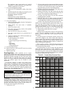
Water Valve (Slow Opening) — If relay is config-
ured for Water Valve (slow opening), the relay will start
60 seconds prior to starting compressor relay.
Outside Air Damper (OAD) — If relay is configured
for OAD, the relay will normally be ON any time the Fan
Enable relay is energized. The relay will not start for
30 minutes following a return to normal mode from NSB,
when NSB is no longer connected to ground C. After 30 min-
utes, the relay will start if the Fan Enable is set to ON.
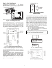
START-UP
Use the procedure outlined below to initiate proper unit
start-up.
NOTE: This equipment is designed for indoor installation only.
Operating Limits
ENVIRONMENT — This equipment is designed for indoor
installation ONLY. Extreme variations in temperature, hu-
midity and corrosive water or air will adversely affect the
unit performance, reliability and service life.
POWER SUPPLY — A voltage variation of ± 10% of
nameplate utilization voltage is acceptable.
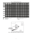
UNIT STARTING CONDITIONS — Depending on the
model, units start and operate in an ambient temperature of
45 F with entering-air temperature at 40 F or 50 F, entering-
water temperature at 20 F or 50 F and with both air and water at
the flow rates used.
NOTE: These operating limits are not normal or continuous
operating conditions. Assume that such a start-up is for the
purpose of bringing the building space up to occupancy
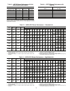
temperature. See Table 14 for operating limits.
1. Restore power to system.
2. Turn thermostat fan position to ON. Blower should
start.
3. Balance airflow at registers.
4. Adjust all valves to the full open position and turn on
the line power to all heat pump units.
5. Operate unit in the cooling cycle first, then the heating
cycle. Refer to Table 14 for unit operating limits. Al-
low 15 minutes between cooling and heating tests for
pressure to equalize.
NOTE: Two factors determine the operating limits of a unit:
entering-air temperature and water temperature. Whenever
any of these factors are at a minimum or maximum level,
the other two factors must be at a normal level to ensure
proper unit operation. See Table 14.
ACCESSORY 1
RELAY OPTIONS
DIP SWITCH POSITION
123
Cycle with Fan On On On
Digital NSB Off On On
Water Valve — Slow Opening On Off On
OAD On On Off
NSB — Night Setback
OAD — Outside Air Damper
ACCESSORY 2
RELAY OPTIONS
DIP SWITCH POSITION
456
Cycle with Fan On On On
Digital NSB Off On On
Water Valve — Slow Opening On Off On
OAD On On Off
NSB — Night Setback
OAD — Outside Air Damper
CAUTION
To avoid equipment damage, DO NOT leave system filled
in a building without heat during the winter unless anti-
freeze is added to system water. Condenser coils never
fully drain by themselves and will freeze unless winterized
with antifreeze.
WARNING
When the disconnect switch is closed, high voltage is
present in some areas of the electrical panel. Exercise
caution when working with the energized equipment.
Failure to heed this warning could lead to personal
injury.