


37
operate if the loop pump status is off and therefore the WSHP
compressor will not run.
COMPLETE C AND DELUXE D BOARD
SYSTEM TEST
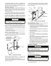
System testing provides the ability to check the control
operation. The control enters a 20-minute Test mode by
momentarily shorting the test pins. All time delays are in-
creased 15 times. See Fig. 13-17.
Test Mode — To enter Test mode on Complete C or Deluxe
D controls, cycle the fan 3 times within 60 seconds. The LED
(light-emitting diode) will flash a code representing the last fault
when entering the Test mode. The alarm relay will also power on
and off during Test mode. See Tables 26-28. To exit Test mode,
short the terminals for 3 seconds or cycle the fan 3 times within
60 seconds.
NOTE: Deluxe D control has a flashing code and alarm relay
cycling code that will both have the same numerical label.
For example, flashing code 1 will have an alarm relay cycling
code 1. Code 1 indicates the control has not faulted since the
last power off to power on sequence.
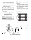
WSHP Open Test Mode — To enter WSHP Open test
mode, navigate from the BACview
6
home screen to the config-
uration screen. Choose the service screen and enable unit test.
The controller will then test the following:
FAN TEST — Tests all fan speeds, sequences fan from low to
high, and operates each speed for one minute. Resets to disable
on completion.
COMPRESSOR TEST — Tests compressor cooling and
heating operation. Sequences cooling stage 1 then cooling
stage 2 followed by heating stage 2 then reduces capacity to
heating stage 1. Operates for 1 minute per step.
DEHUMIDIFICATION TEST — Tests dehumidification
mode. Operates for 2 minutes.
AUXILIARY HEATING TEST — Tests auxiliary heat.
Sequences fan on and enables heating coil for 1 minute.
H
2
O ECONOMIZER TEST — Tests entering/returning
water loop economizer operation. Sequences fan and opens
economizer water valve for one minute.
OPEN VENT DAMPER 100% TEST — Tests outside air
(OA) damper operation.
PREPOSITION OA DAMPER — Prepositions OA damper
actuator to set proper preload.
NOTE: The auxiliary heating test, H
2
O economizer test, open
vent damper 100% test, and preposition OA damper features
will not be visible on the screen unless configured.
Once tests are complete, set unit test back to disable. Unit will
automatically reset to disable after 1 hour.
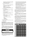
Retry Mode — In Retry mode, the status LED will start to
flash slowly to signal that the control is trying to recover from
an input fault. The control will stage off the outputs and try to
again satisfy the thermostat used to terminal Y. Once the ther-
mostat input calls are satisfied, the control will continue normal
operation.
NOTE: If 3 consecutive faults occur without satisfying the
thermostat input call to terminal Y, the control will go into
lockout mode. The last fault causing the lockout is stored in
memory and can be viewed by entering Test mode.
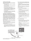
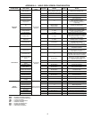
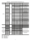
Aquazone™ Deluxe D Control LED Indica-
tors — There are 3 LED indicators on the Deluxe D control:
STATUS LED — Status LED indicates the current status or
mode of the Deluxe D control. The Status LED light is green.
TEST LED — Test LED will be activated any time the De-
luxe D control is in test mode. The Test LED light is yellow.
FAULT LED — Fault LED light is red. The fault LED will al-
ways flash a code representing the last fault in memory. If there
is no fault in memory, the fault LED will flash code 1 on the
and appear as 1 fast flash alternating with a 10-second pause.
See Table 28.
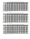
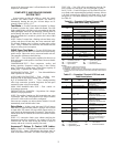
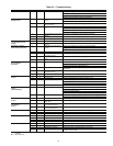
Table 26 — Complete C Control Current LED
Status and Alarm Relay Operations
LEGEND
NOTES:
1. Slow flash is 1 flash every 2 seconds.
2. Fast flash is 2 flashes every 1 second.
3. EXAMPLE: “Flashing Code 2” is represented by 2 fast flashes followed by
a 10-second pause. This sequence will repeat continually until the fault is
cleared.
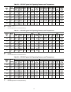
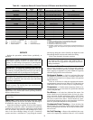
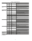
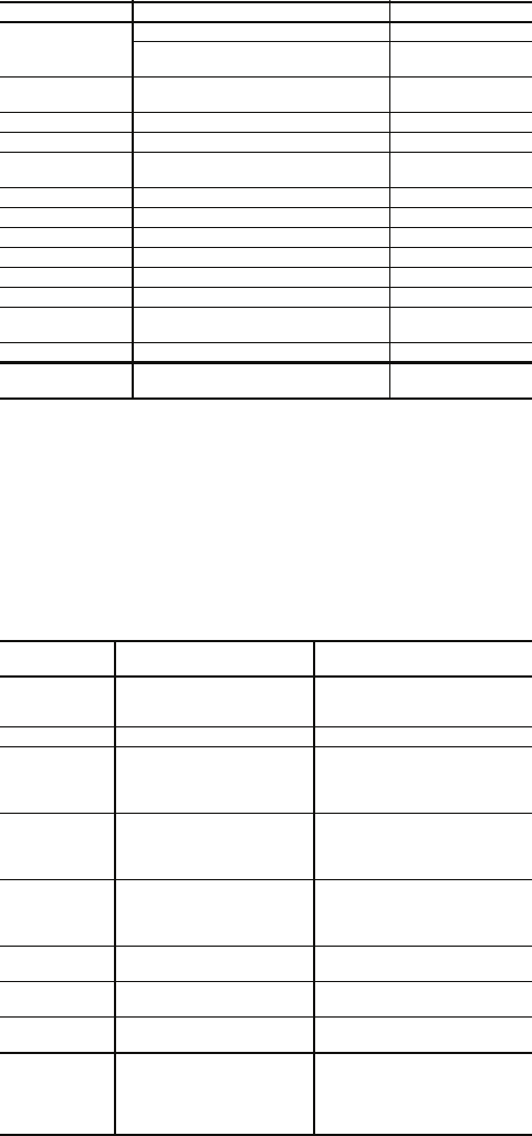
Table 27 — Complete C Control LED Code and
Fault Descriptions
LEGEND
LED STATUS DESCRIPTION OF OPERATION ALARM RELAY
On
Normal Mode Open
Normal Mode with PM Warning
Cycle (closed 5
sec., Open 25 sec.)
Off
Complete C Control is
non-functional
Open
Slow Flash Fault Retry Open
Fast Flash Lockout Closed
Slow Flash Over/Under Voltage Shutdown
Open (Closed after
15 minutes)
Flashing Code 1 Test Mode — No fault in memory Cycling Code 1
Flashing Code 2 Test Mode — HP Fault in memory Cycling Code 2
Flashing Code 3 Test Mode — LP Fault in memory Cycling Code 3
Flashing Code 4 Test Mode — FP1 Fault in memory Cycling Code 4
Flashing Code 5 Test Mode — FP2 Fault in memory Cycling Code 5
Flashing Code 6 Test Mode — CO Fault in memory Cycling Code 6
Flashing Code 7
Test Mode — Over/Under shutdown
in memory
Cycling Code 7
Flashing Code 8 Test Mode — PM in memory Cycling Code 8
Flashing Code 9
Test Mode — FP1/FP2 Swapped
Fault in memory
Cycling Code 9
CO — Condensate Overflow LED — Light-Emitting Diode
FP — Freeze Protection LP — Low Pressure
HP — High Pressure PM — Performance Monitor
LED
CODE
FAULT DESCRIPTION
1 No fault in memory There has been no fault since
the last power-down to power-
up sequence
2 High-Pressure Switch HP open instantly
3 Low-Pressure Switch LP open for 30 continuous
seconds before or during a
call (bypassed for first 60 sec-
onds)
4 Freeze Protection
Coax — FP1
FP1 below Temp limit for 30
continuous seconds
(bypassed for first 60 seconds
of operation)
5 Freeze Protection Air Coil
— FP2
FP2 below Temp limit for 30
continuous seconds
(bypassed for first 60 seconds
of operation)
6 Condensate overflow Sense overflow (grounded)
for 30 continuous seconds
7 (Autoreset) Over/Under Voltage
Shutdown
"R" power supply is <19VAC
or >30VAC
8 PM Warning Performance Monitor Warning
has occurred.
9 FP1 and FP2
Thermistors are swapped
FP1 temperature is higher
than FP2 in heating/test
mode, or FP2 temperature is
higher than FP1 in cooling/
test mode.
FP — Freeze Protection LP — Low Pressure
HP —
High Pressure PM — Performance Monitor
LED — Light-Emitting Diode