


26
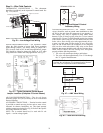
FIELD SELECTABLE INPUTS
Jumpers and DIP (dual in-line package) switches on the
control board are used to customize unit operation and can be
configured in the field.
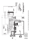
Complete C Control Jumper Settings (Refer to
Fig. 13 and 16)
WATER COIL FREEZE PROTECTION (FP1) LIMIT
SETTING — Select jumper 3, (JW3-FP1 Low Temp) to
choose FP1 limit of 10 F or 30 F. To select 30 F as the limit,
DO NOT clip the jumper. To select 10 F as the limit, clip the
jumper.
AIR COIL FREEZE PROTECTION (FP2) LIMIT SET-
TING — Select jumper 2 (JW2-FP2 Low Temp) to choose
FP2 limit of 10 F or 30 F. To select 30 F as the limit, DO NOT
clip the jumper. To select 10 F as the limit, clip the jumper.
ALARM RELAY SETTING — Select jumper 1 (JW1-AL2
Dry) for connecting alarm relay terminal (AL2) to 24 vac (R)
or to remain as a dry contact (no connection). To connect AL2
to R, do not clip the jumper. To set as dry contact, clip the
jumper.
Complete C Control DIP Switches — The Con-
plete C control has 1 DIP switch block with two switches.
Refer to Fig. 13 and 16.
PERFORMANCE MONITOR (PM) — DIP switch 1 will
enable or disable this feature. To enable the PM, set the switch
to ON. To disable the PM, set the switch to OFF.
STAGE 2 — DIP switch 2 will enable or disable compressor
delay. Set DIP switch to OFF for stage 2 in which the compres-
sor will have a 3-second delay before energizing.
NOTE: The alarm relay will not cycle during Test mode if
switch is set to OFF, stage 2.
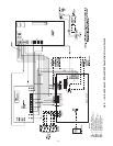
Deluxe D Control Jumper Settings (Refer to
Fig. 14, 15, and 17)
WATER COIL FREEZE PROTECTION (FP1) LIMIT
SETTING — Select jumper 3, (JW3-FP1 Low Temp) to
choose FP1 limit of 10 F or 30 F. To select 30 F as the limit,
DO NOT clip the jumper. To select 10 F as the limit, clip the
jumper.
AIR COIL FREEZE PROTECTION (FP2) LIMIT SET-
TING — Select jumper 2 (JW2-FP2 Low Temp) to choose
FP2 limit of 10 F or 30 F. To select 30 F as the limit, DO NOT
clip the jumper. To select 10 F as the limit, clip the jumper.
ALARM RELAY SETTING — Select jumper 4 (JW4-AL2
Dry) for connecting alarm relay terminal (AL2) to 24 vac (R)
or to remain as a dry contact (no connection). To connect AL2
to R, do not clip the jumper. To set as dry contact, clip the
jumper.
LOW PRESSURE SETTING — The Deluxe D control can
be configured for Low Pressure Setting (LP). Select jumper 1
(JW1-LP Norm Open) for choosing between low pressure in-
put normally open or closed. To configure for normally closed
operation, do not clip the jumper. To configure for normally
open operation, clip the jumper.
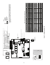
Deluxe D Control DIP Switches — The Deluxe D
control has 2 DIP switch blocks. Each DIP switch block has 8
switches and is labeled either S1 or S2 on the circuit board.
Refer to Fig. 14, 15, and 17.
DIP SWITCH BLOCK 1 (S1) — This set of switches offers
the following options for Deluxe D control configuration:
Performance Monitor (PM)
— Set switch 1 to enable or dis-
able performance monitor. To enable the PM, set the switch to
ON. To disable the PM, set the switch to OFF.
Compressor Relay Staging Operation
— Switch 2 will en-
able or disable compressor relay staging operation. The com-
pressor relay can be set to turn on with stage 1 or stage 2 call
from the thermostat. This setting is used with dual stage units
(units with 2 compressors and 2 Deluxe D controls) or in mas-
ter/slave applications. In master/slave applications, each com-
pressor and fan will stage according to its switch 2 setting. If
switch is set to stage 2, the compressor will have a 3-second de-
lay before energizing during stage 2 demand.
NOTE: If DIP switch is set for stage 2, the alarm relay will not
cycle during Test mode.
Heating/Cooling Thermostat Type
— Switch 3 provides selec-
tion of thermostat type. Heat pump or heat/cool thermostats
can be selected. Select OFF for heat/cool thermostats. When in
heat/cool mode, Y1 is used for cooling stage 1, Y2 is used for
cooling stage 2, W1 is used for heating stage 1 and O/W2 is
used for heating stage 2. Select ON for heat pump applications.
In heat pump mode, Y1 used is for compressor stage 1, Y2 is
used for compressor stage 2, W1 is used for heating stage 3 or
emergency heat, and O/W2 is used for RV (heating or cooling)
depending upon switch 4 setting.
O/B Thermostat Type
— Switch 4 provides selection for heat
pump O/B thermostats. O is cooling output. B is heating out-
put. Select ON for heat pumps with O output. Select OFF for
heat pumps with B output.
Dehumidification Fan Mode
— Switch 5 provides selection
of normal or dehumidification fan mode. Select OFF for dehu-
midification mode. The fan speed relay will remain OFF dur-
ing cooling stage 2. Select ON for normal mode. The fan speed
relay will turn on during cooling stage 2 in normal mode.
Switch 6
— Not used.
Boilerless Operation
— Switch 7 provides selection of boiler-
less operation and works in conjunction with switch 8. In
boilerless operation mode, only the compressor is used for
heating when FP1 is above the boilerless changeover tempera-
ture set by switch 8 below. Select ON for normal operation or
select OFF for boilerless operation.
Boilerless Changeover Temperature
— Switch 8 on S1 pro-
vides selection of boilerless changeover temperature set point.
Select OFF for set point of 50 F or ON for set point of 40 F.
If switch 8 is set for 50 F, then the compressor will be used
for heating as long as the FP1 is above 50 F. The compressor
will not be used for heating when the FP1 is below 50 F and the
compressor will operates in emergency heat mode, staging on
EH1 and EH2 to provide heat. If a thermal switch is being used
instead of the FP1 thermistor, only the compressor will be used
for heating mode when the FP1 terminals are closed. If the FP1
terminals are open, the compressor is not used and the control
goes into emergency heat mode.
DIP SWITCH BLOCK 2 (S2) — This set of DIP switches is
used to configure accessory relay options. Refer to Fig. 14, 15,
and 17.
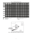
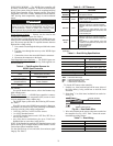
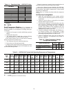
Switches 1 to 3
— These DIP switches provide selection
of Accessory 1 relay options. See Table 12 for DIP switch
combinations.
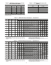
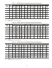
Switches 4 to 6
— These DIP switches provide selection
of Accessory 2 relay options. See Table 13 for DIP switch
combinations.
IMPORTANT: Jumpers and DIP switches should only
be clipped when power to control board has been turned
off.