


10
Insulation is not required on loop water piping except where
the piping runs through unheated areas or outside the building
or when the loop water temperature is below the minimum ex-
pected dew point of the pipe ambient. Insulation is required if
loop water temperature drops below the dew point.
Pipe joint compound is not necessary when Teflon threaded
tape is pre-applied to hose assemblies or when flared-end
connections are used. If pipe joint compound is preferred, use
compound only in small amounts on the male pipe threads of
the fitting adapters. Prevent sealant from reaching the flared
surfaces of the joint.
NOTE: When anti-freeze is used in the loop, assure that it is
compatible with Teflon tape or pipe joint compound employed.
Maximum allowable torque for brass fittings is 30 ft-lb. If a
torque wrench is not available, tighten finger-tight plus one
quarter turn. Tighten steel fittings as necessary.
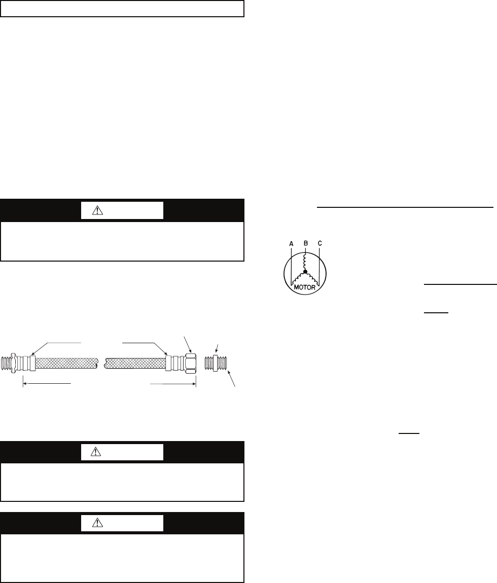
Optional pressure-rated hose assemblies designed specifi-
cally for use with Carrier units are available. Similar hoses can
be obtained from alternate suppliers. Supply and return hoses
are fitted with swivel-joint fittings at one end to prevent kink-
ing during installation.
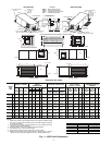
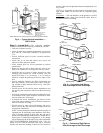
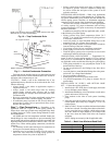
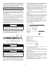
Refer to Fig. 12 for an illustration of a supply/return hose
kit. Male adapters secure hose assemblies to the unit and risers.
Install hose assemblies properly and check them regularly to
avoid system failure and reduced service life.
Step 8 — Wire Field Power Supply
All field installed wiring, including the electrical ground,
MUST comply with the National Electrical Code (NEC) as
well as applicable local codes. In addition, all field wiring must
conform to the Class II temperature limitations described in the
NEC.
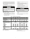
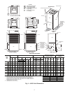
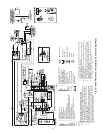
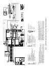
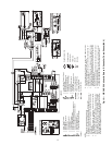
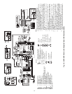
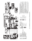
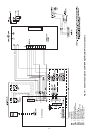
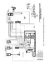
Refer to unit wiring diagrams Fig. 13-22 for a schematic of
the field connections, which must be made by the installing (or
electrical) contractor. Refer to Table 3 for fuse sizes.
Consult the unit wiring diagram located on the inside of the
compressor access panel to ensure proper electrical hookup.
The installing (or electrical) contractor must make the field
connections when using field-supplied disconnect.
Operating voltage must be the same voltage and phase as
shown in Table 3.
Make all final electrical connections with a length of flexi-
ble conduit to minimize vibration and sound transmission to
the building.
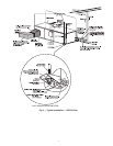
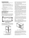
POWER CONNECTION — Make line voltage connection
by connecting the incoming line voltage wires to the L side
of the CC terminal as shown in Fig. 23. See Table 3 for cor-
rect wire and maximum overcurrent protection sizing.
SUPPLY VOLTAGE — Operating voltage to unit must be
within voltage range indicated on unit nameplate.
On 3-phase units, voltages under load between phases must
be balanced within 2%. Use the following formula to deter-
mine the percentage voltage imbalance:
% Voltage Imbalance
Example: Supply voltage is 460-3-60.
AB = 452 volts
BC = 464 volts
AC = 455 volts
Determine maximum deviation from average voltage:
(AB) 457 – 452 = 5 v
(BC) 464 – 457 = 7 v
(AC) 457 – 455 = 2 v
Maximum deviation is 7 v.
Determine percent voltage imbalance.
This amount of phase imbalance is satisfactory as it is
below the maximum allowable 2%.
Operation on improper line voltage or excessive phase
imbalance constitutes abuse and may cause damage to electri-
cal components.
NOTE: If more than 2% voltage imbalance is present, contact
your local electric utility.
208-VOLT OPERATION — All 208-230 volt units are factory
wired for 208 volts. The transformers may be switched to
230-volt operation by switching the red (208 volt) wire with
the orange (230 volt) wire at the L1 terminal.
460-VOLT OPERATION — Units using 460-v and internal
secondary pump will require a neutral wire from the supply
side in order to feed accessory with 265-v.
IMPORTANT: Do not bend or kink supply lines or hoses.
CAUTION
Backup wrench is required when tightening water connec-
tions to prevent water line damage. Failure to use a backup
wrench could result in equipment damage.
WARNING
To avoid possible injury or death due to electrical shock,
open the power supply disconnect switch and secure it in
an open position during installation.
CAUTION
Use only copper conductors for field-installed electrical
wiring. Unit terminals are not designed to accept other
types of conductors. Failure to follow this safety precaution
could lead to equipment damage.
= 100 x
max voltage deviation from average voltage
average voltage
Average Voltage =
452 + 464 + 455
3
=
1371
3
= 457
% Voltage Imbalance = 100 x
7
457
= 1.53%
Rib Crimped
Length
(2 ft Length Standard)
Swivel
Brass
Fitting
Brass
Fitting
MPT
Fig. 12 — Supply/Return Hose Kit
A50-7734