


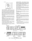
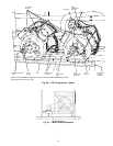
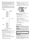

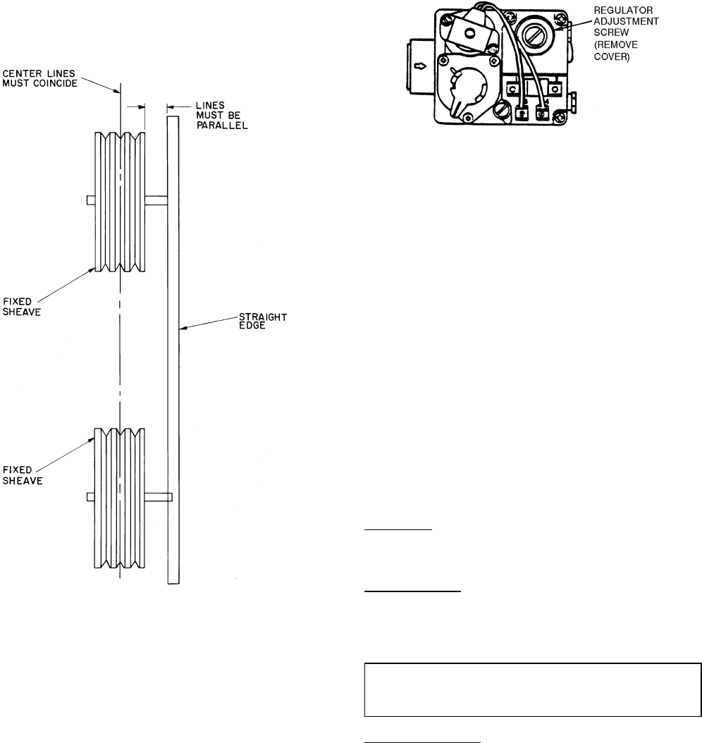
PULLEY ALIGNMENT — For proper belt life, the motor
and fan pulleys must be properly aligned. To check, first turn
off unit power. Place a straightedge against the motor and
fan pulleys. See Fig. 62. If the pulleys are properly aligned,
the straightedge should be parallel to the belts.
If they are not parallel, check that the motor shaft and fan
shaft are parallel. If they are not, adjust the motor plate
adjusting bolts until they are.
After verifying that the shafts are parallel, loosen the set-
screws on the motor pulley. Move pulley on the shaft until
the pulleys are parallel. To move the sheave on the shaft,
loosen the belts. If necessary, blower sheave can alsobe moved
on the shaft.
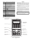
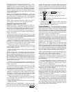
Gas Valve Adjustment
NATURAL GAS — The gas valve opens and closes in re-
sponse to the PIC control or limit control.
When power is supplied to valve terminals D1 and C2,
the main valve opens to its preset position.
The regular factory setting is stamped on the valve body
(3.3 in. wg).
To adjust regulator:
1. Set thermostat at setting for no call for heat.
2. Turn main gas valve to OFF position.
3. Remove
1
⁄
8
-in. pipe plug from manifold or gas valve pres-
sure tap connection. Install a suitable pressure-measuring
device.
4. Set main gas valve to ON position.
5. Set thermostat at setting to call for heat.
6. Remove screw cap covering regulator adjustment screw
(see Fig. 63).
7. Turn adjustment screw clockwise to increase pressure or
counterclockwise to decrease pressure.
8. Once desired pressure is established, set thermostat set-
ting for no call for heat, turn off main gas valve, remove
pressure-measuring device, and replace
1
⁄
8
-in. pipe plug
and screw cap.
Main Burners — For all applications, main burners are
factory set and should require no adjustment.
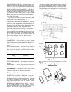
MAIN BURNER REMOVAL
1. Shut off (field-supplied) manual main gas valve.
2. Shut off power to unit.
3. Remove gas section access door, door frame, and corner
post.
4. Disconnect gas piping from gas valve inlet.
5. Remove wires from gas valve.
6. Remove wires from rollout switch.
7. Remove sensor wire and ignitor cable from IGC board.
8. Remove 2 screws securing manifold bracket to
basepan.
9. Remove 2 screws that hold the burner support plate flange
to the vestibule plate.
10. Lift burner assembly out of unit.
Protective Devices
COMPRESSOR PROTECTION
Overcurrent — Each compressor has one manual reset, cali-
brated trip, magnetic circuit breaker. Do not bypass connec-
tions or increase thesize of the circuit breaker tocorrect trouble.
Determine the cause and correct it before resetting the breaker.
Crankcase Heater — Each compressor has a crankcase heater
to prevent absorption of liquid refrigerant by oil in the crank-
case when the compressor is idle. Since 115-v power for the
crankcase heaters is drawn from the unit control circuit, main
unit power must be on for the heaters to be energized.
IMPORTANT: After a prolonged shutdown or service
job, energize the crankcase heaters for 24 hours before
starting the compressor.
Compressor Lockout — If any of the safeties (high-pressure,
or low-pressure) trip, or if there is a loss of power to the
compressors, the compressors will be locked out. To reset,
consult the controls and troubleshooting literature for the
appropriate unit for details.
EVAPORATOR-FAN MOTOR PROTECTION —A manual
reset, calibrated trip, magnetic circuit breaker protects against
overcurrent. Do not bypass connections or increase the size
of the breaker to correct trouble. Determine the cause and
correct it before resetting the breaker.
Fig. 62 — Pulley Alignment
Fig. 63 — Gas Valve
52