


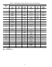
Table 30 — Variable Frequency Drive (VFD) Display
DISPLAY ACTION
Fref Not used.
Fout
Displays the output frequency at which the VFD is cur-
rentlyoperating. Thisisadisplay onlyfunction.Theuser
cannot change this displayed value.
lout
Displays the level ofoutput current that theVFD is cur-
rentlyproducing.This isadisplayonly function.Theuser
cannot change this displayed value.
kWout
Displaysthe outputpower thattheVFD iscurrentlypro-
ducing. Thisis a display onlyfunction. The usercannot
change this displayed value.
F/R
Setsthe rotationdirection ofthemotor whenarun com-
mand is given.
Montr
Press to access the monitor parameters
ENTER
(U-01 through U-13).
Accel Not used.
Decel Not used.
Vmtr Sets the rated voltage of the motor.
V/F
Sets a presetV/f pattern or allows acustom V/f pattern
to be set.
Fgain
Sets the frequency reference gain for the analog fre-
quency reference.
Fbias
Sets the frequency reference bias for the analog fre-
quency reference.
FLA
Sets the full load amps used for detecting motor over-
load. When FLA is set to 0 it is disabled.
PID Enables or disables the PID.
kWsav Enables or disables the energy saving function.
PRGM Allows parameter programming.
LEGEND
PID — Proportional Integral Derivative
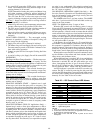
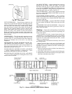
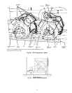
SERVICE
Service Access —
All unit components can be reached
through clearly labeled hinged access doors. These doors are
equipped with tiebacks, but if heavy duty servicing is needed,
it is recommended that the doors be removed or propped open.
Each door is held closed with 3 latches. The latches are
secured to the unit with a single
1
⁄
4
-in. Ϫ20 x
1
⁄
2
-in. long
bolt. See Fig. 50.
To open, loosen the latch bolt using a 7/16-in. wrench.
Pivot the latch so it is not in contact with the door. Open the
door. To shut, reverse the above procedure.
NOTE: Disassembly of the top cover may be required under
special service circumstances. It is very important that the
orientation and position of the top cover be marked on the
unit prior to disassembly. This will allow proper replace-
ment of the top cover onto the unit and prevent rainwater
from leaking into the unit.
IMPORTANT:After servicing is completed, make sure
door is closed and relatched properly, and thatthe latches
are tight. Failure to do this can result in water leakage
into the indoor-air section of the unit.
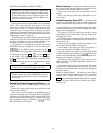
PGRM
Fbias
Fref
F/R
Vmtr
FLA PID
V / F
Montr
Fout lout
Accel
kWout
Decel
Fgain
kWsav
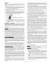
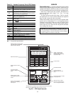
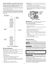
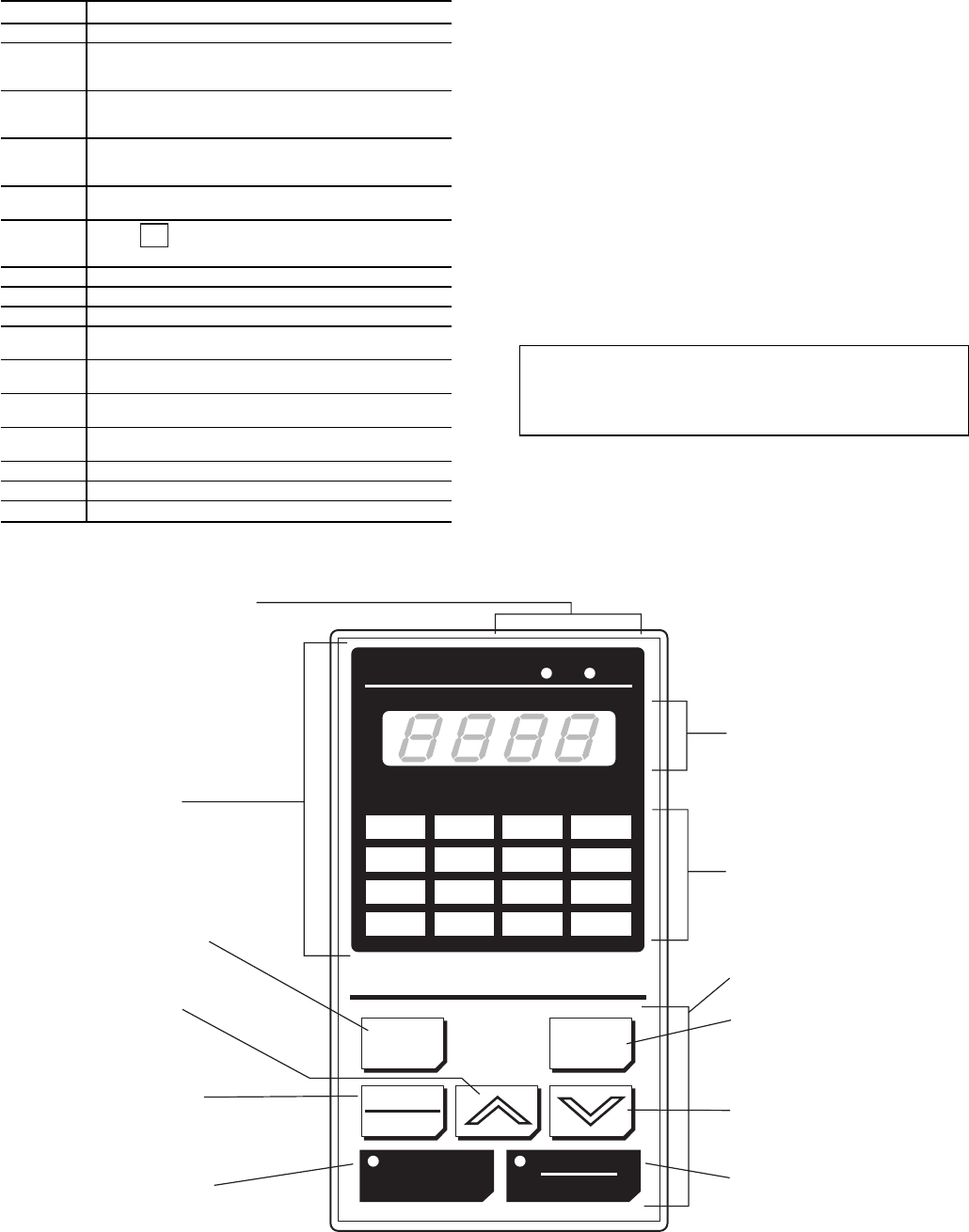
DIGITAL OPERATOR
JVOP-131
SEQ
REF
DSPL
ENTER
LOCAL
REMOTE
REMOTE
RUN
STOP
RESET
4-digit, 7-segment LED
display; shows selected
operation status, fault code,
or parameter data.
Function LEDs
KEYPAD SECTION
Displays data to be
changed, and enters new
data.*
Decrease parameter number
or displayed value.
Stop the motor, or reset a
drive fault. LED lights when
drive is in stopped condition.
REMOTE Mode indication LEDs.
The LEDs light when REMOTE
Mode has been selected.
DISPLAY SECTION
Switch between Function
LEDs*
Increase parameter
number or displayed
value.
Switch between LOCAL
and REMOTE operation
modes.
Run the motor. LED lights
when drive is controlling
motor speed.
*Pressing DSPL and ENTER keys simultaneously allows all parameter
data to be read, but not set, while the drive is running.
Fig. 49 — VFD Digital Operator
45