


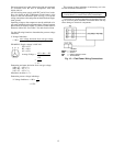
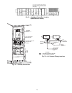

Carrier Comfort Network Interface — The
48/50MP units can be connected to the CCN if desired. The
communication bus wiring is supplied and installed in
the field. It consists of shielded, 3-conductor cable with
drain wire.
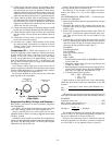
The system elements are connected to the communication
bus in a daisy chain arrangement. The positive pin of each
system element communication connector must be wired to
the positive pins of the system element on either side of it,
the negative pins must be wired to the negative pins, and the
signal pins must be wired to signal ground pins. Wiring con-
nections for CCN should be made at the 4-pin plug (COMM)
located at the bottom right side of the fuse bracket in the
main control box. Consult CCN Contractor’s Manual for fur-
ther information.
NOTE: Conductors and drain wire must be 20 AWG mini-
mum stranded, tinned copper. Individual conductors must
be insulated with PVC, PVC/nylon, vinyl, Teflon, or poly-
ethylene. An aluminum/polyester 100% foil shield and an
outer jacket of PVC, PVC/nylon, chrome vinyl, or Teflon
with a minimum operating temperature range of Ϫ20 C to
60 C is required. See Table 7 for cables that meet the
requirements.
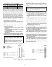
Table 7 — CCN Connection Approved
Shielded Cables
MANUFACTURER CABLE PART NO.
Alpha 2413 or 5463
American A22503
Belden 8772
Columbia 02525
IMPORTANT: When connecting the CCN communi-
cation bus to a system element, use a color coding sys-
tem for the entire network to simplify installation and
checkout.
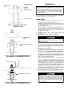
T3
T2
T1
GROUND
L1
L2
L3
(R)
(S)
(T)
FI
FC
S1
SC
3
1
IFR (SUPPLY
PER (EXHAUST)
VOLTAGE
SELECTOR
G
46
47
+
-
43
44
PECB (EXHAUST)
IFCB (SUPPLY)
PEC (EXHAUST)
IFC (SUPPLY)
L3
L2
L1
VFD
460V
SHIELD
(SUPPLY)
PSIO1
J6
CHANNEL 16
(EXHAUST)
PSIO1
J6
CHANNEL 15
+
-
EFM
(EXHAUST)
IDFM
(SUPPLY)
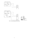
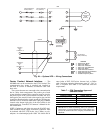
LEGEND
EFM — Exhaust Fan Motor
IDFM — Indoor Fan Motor
IFC — Indoor Fan Contactor
IFCB — Indoor Fan Circuit Breaker
IFR — Indoor Fan Relay
PEC — Power Exhaust Contactor
PECB — Power Exhaust Circuit Breaker
PER — Power Exhaust Relay
VFD — Variable Frequency Drive
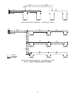
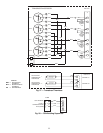
Fig. 29 — Optional VFD — Wiring Connections
23