


KEYPAD AND DISPLAY MODULE (HSIO)
IMPORTANT: The HSIO (human sensor input/output)
keypad and display module is required for initial start-up
of these units. All units are shipped in standby mode,
and the HSIO must be used to change the unit to run
mode. Once the unit is in run mode, the HSIO is not
required for normal operation.
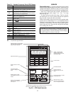
The keypad and display module HSIO (or local interface
device, LID, factory-installed and located in the main
control box) provides unit function information at the unit.
The module consists of a keypad with 6 function keys,
5 operative keys, 10 numeric keys (0 through 9), and an
alphanumeric 8-character liquid crystal display (LCD). Key
usage is explained in Table 23. Each function has one or more
subfunctions as shown in Table 29.
The HSIO keypad and display module is installed through
connection of the power and communication plugs and can
be easily moved from one unit to another. Because of this
flexibility, one HSIO can be used for several units.
Unit operation is controlled by the status of the RUN/
STANDBY mode on the HSIO. To access the mode, press
on the HSIO keypad, and then use the
key. The HSIO will display either STBY YES or STBY NO.
CLEAR
ENTER
To enable the unit, press or and press while
at the STBY YES display. To disable the unit, press
ENTER
while at the STBY NO display. Clearing an alarm
that has stopped unit operation is accomplished by entering
the STBY YES mode.
IMPORTANT: Use the STBY YES mode when ser-
vicing the unit or running the Quick Test feature.
IMPORTANT: If unit is also equipped with REMOTE
START function, place LOCAL/REMOTE switch in
LOCAL (Off) position when servicing or running Quick
Test feature.
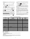
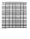
Default Set Points/Changing Set Points — Re-
fer to Table 24 for factory default configuration and set point
values.
Record any changes made during start-up and leave with
unit for future reference.
These values may be changed from the HSIO keypad at
any time. If changing values via Service Tool or CCN Build-
ing Supervisor, the unit must be in RUN mode (STBY NO),
which is done through HSIO input or a Remote Start input.
After changing the values in subfunction , the Data
Reset function must be enabled.
Motor Protection — Manual reset, calibrated trip, mag-
netic circuit breakers are provided for each compressor, sup-
ply fan motor, and optional exhaust fan motor.
Outdoor fan motor circuits are also protected by circuit
breakers.
Refer to the Service section more information on serv-
icing motors.
Variable Frequency Drive (VFD) — An optional VFD
can be factory-installed and is used to modulate supply fan
airflow to maintain duct static pressure on VAV applications.
A second VFD can be used to modulate exhaust fan airflow
to maintain building pressure on units equipped with modu-
lating power exhaust option.
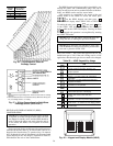
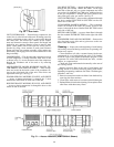
The supply fan VFD is located in the auxiliary control
compartment, on the left hand side of the unit, at the end of
the supply fan section.
The modulating power exhaust VFD is located in the ex-
haust fan compartment, on the right hand side of the unit, at
the return air end.
Control input to the supply fan VFD is provided bya4to
20 mA signal from the PSIO1 (Channel 16).
Control input to the exhaust fan VFD is provided by a
4 to 20 mA signal from the PSIO1 (Channel 15).
Set point control for the VFD is done through the HSIO
or other network devices (subfunction ). Refer to the
Controls and Troubleshooting manual for configuration in-
structions and sequence of operation.
The VFD has been programmed at the factory for 48/
50MP applications. No further adjustments should be nec-
essary at start-up.
A separate technical and service manual for the factory
installed VFD is supplied with each unit. Refer to the VFD
manual for more information on accessing and diagnosing
the VFD controls.
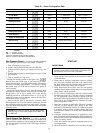
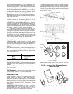
DISPLAY AND KEYPAD — All functions of the VFD are
accessed using the Digital Operator. See Fig. 49. The Digital
Operator has a 4-digit LED display. By pressing the
DSPL
key on the Digital Operatorwhile the drive is stopped,
the user can step to each of the 16 functions and displays.
See Table 30.
43