


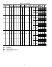

The following color code is recommended:
SIGNAL
TYPE
CCN BUS CONDUCTOR
INSULATION COLOR
COMM1 PLUG
PIN NO.
ϩ RED 1
GROUND WHITE 2
Ϫ BLACK 3
NOTE: If a cable with a different color scheme is selec-
ted, a similar color code should be adopted for the entire
network.
At each system element, the shields of its communication
bus cables must be tied together. If the communication
bus is entirely within one building, the resulting continuous
shield must be connected to a ground at one point only. If
the communication bus cable exits from one building and
enters another, the shields must be connected to grounds at
the lightning suppressor in each building where the cable
enters or exits the building (one point per building only).
To connect the unit to the network:
1. Turn off power to the control box.
2. Cut the CCN wire and strip the ends of the red (ϩ), white
(ground) and black (Ϫ) conductors. (If a different net-
work color scheme is used, substitute appropriate
colors.)
3. Remove the 4-pin female plug from the fuse and control
circuit breaker bracket in the main control box, and con-
nect the wires as follows:
a. Insert and secure the red (ϩ) wire to terminal 1 of the
4-pin plug.
b. Insert and secure the white (ground) wire to terminal
2 of the 4-pin plug.
c. Insert and secure the black (Ϫ) wire to terminal 3 of
the 4-pin plug.
4. Insert the plug into the existing 4-pin mating connector
on the fuse or control circuit breaker bracket in the main
control box.
IMPORTANT: A shorted CCN bus cable will pre-
vent some routines from running and may prevent
unit from starting. If abnormal conditions occur, un-
plug the connector. If conditions return to normal,
check CCN connector, and run new cable if nec-
essary. A short in one section of the bus can cause
problems with all system elements on the bus.
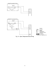
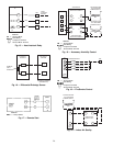
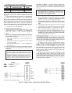
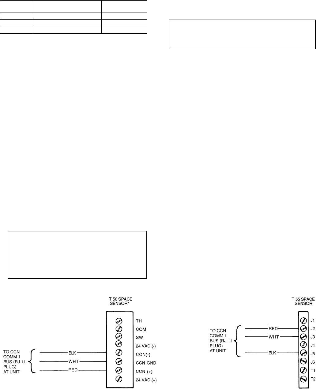
RJ11 PLUG WIRING — Units on the CCN can be moni-
tored from the space at the sensor through the RJ11 con-
nector, if desired. To wire the RJ11 connector into the CCN
(Fig. 30):
IMPORTANT: The cable selected for the RJ11 con-
nector wiring MUST be identical to the CCN com-
munication bus wire used for the entire network. Re-
fer to Table 7 for acceptable wiring.
1. Cut the CCN wire and strip ends of the red (ϩ), white
(ground), and black (Ϫ) conductors. (If another wire color
scheme is used, strip ends of appropriate wires.)
2. Insert and secure the red (ϩ) wire to pin J2 (T-55) or CCN
+ (T-56) of the space temperature sensor terminal block
(TB1).
3. Insert and secure the white (ground) wire to pin J3 (T-55)
or CCN GND (T-56) of the space temperature sensor TB1.
4. Insert and secure the black (Ϫ) wire to pin J5 (T-55) or
CCN − (T-56) of the space temperature sensor TB1.
5. Connect the other end of the communication bus cable to
the remainder of the CCN communication bus at the
COMM1 plug located onthe fuse and control circuit breaker
bracket in the unit main control box.
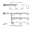
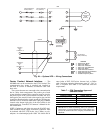
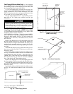
Air Pressure Tubing — Before options such as supply
fan VFD and modulating power exhaust can operate prop-
erly, the pneumatic tubes for pressure sensing must be in-
stalled. The recommended field-supplied tubing for this use
is a nominal
1
⁄
4
-in., fire-retardant tubing.
The tubing must be run from the appropriate location
in the building to the auxiliary control box in the unit.
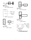
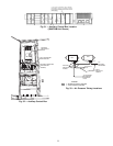
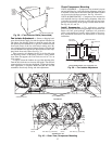
Figures 31 and 32 show the location and layout of the
auxiliary control box in the 48/50MP unit. Figure 33 shows
the connection locations for the tubing on the duct pressure
(DP) controller for the VFD on the supply fan and on the
building pressure (BP) controller for the VFD on the modu-
lating power exhaust fan.
The tubing for the duct pressure control (DP) should sample
supply duct pressure about
2
⁄
3
of the way out from the unit
in the main trunk duct. The tubing for the building pressure
control (BP) should sample building pressure in the area near
the entrance lobby so that location is controlled as closely to
design pressures as possible.
*Constant volume applications only.
Fig. 30 — Space Sensor to Communication Bus Wiring
LEGEND
CCN — Carrier Comfort Network
COM — Common
COMM — Communications
GND — Ground
24