


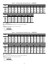

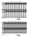
Table 18 — Component Pressure Drop (in. wg)
COMPONENT 22,000 26,400 30,000 34,000 38,000 42,000 45,800 48,200 52,000
HEAT EXCHANGER
(48MP ONLY)
0.31 0.40 0.49 0.58 0.70 0.82 0.95 1.03 1.23
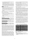
Table 19 — Maximum Allowable
Supply Fan Wheel Speed (Rpm)
48/50MP
FAN TYPE
Forward Curved Airfoil
62L, 70M 835 1595
82N, 90P, 10R 715 1298
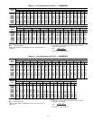
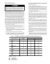
Table 20 — Maximum Allowable Power Exhaust
Fan Speed (Rpm)
48/50MP
FAN TYPE
50% Air 100% Air
62L, 70M 690 650
82N, 90P, 10R 600 560
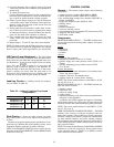
Table 21 — Air Quantity Limits (cfm)
UNIT
SIZE
48/50MP
MINIMUM MAXIMUM
MINIMUM
GAS HEATING
(Low Heat
Units)
48MPD
MINIMUM
GAS HEATING
(High Heat
Units)
48MPE
62L 16,000 32,000 12,850 15,400
70M 18,000 36,000 12,850 15,400
82N 21,000 42,000 14,700 19,250
90P 23,000 46,000 14,700 19,250
10R 26,000 52,000 14,700 19,250
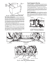
Controls Configuration and Quick Test
SUPPLYFAN STATUS SWITCH (FS)—Asnap acting single-
pole, double-throw (SPDT) differential pressure switch is fac-
tory mounted in the auxiliary control box. The switch senses
the change in pressure across the supply-air fan and pro-
vides the fan status. A length of plenum tubing connects the
switch to the probe located in the fan discharge box.
The switch must be set prior to unit operation. To set the
switch, turn the adjustment screw on top (center) of switch
clockwise to increase set point, or counterclockwise to
decrease set point. The set point switch range is 0.05 to
2.0 in. wg with a deadband of 0.02 in. wg at minimum set
point and 0.1 in. wg at maximum set point.
Set switch so that contact makes to NC when supply-air
fan is energized. The switch should make (fan on) within
1 minute after supply-air fan is energized and break (fan off)
within 1 minute after the fan is deenergized.
CHECK FILTER SWITCH (CFS) — A snap acting SPDT
switch is factory mounted in the auxiliary control box. The
switch senses the differential pressure and provides the micro-
processor module with a signal for filter status. Two lengths
of plenum tubing connect the switch to probes located both
upstream and downstream of the unit filters.
The switch must be set prior to unit operation. To set the
switch, turn the adjustment screw on top (center) of switch
slowly clockwise to find the ‘‘pivot’’ point where the filter
status still reads clean under in the HSIO display.
Check the switch operation with the supply-air fan running
and nominal cfm delivery. See Table 22 for clean filter pres-
sure drops for help in locating the ‘‘pivot’’ point. Once this
point is found, turn the screw clockwise to obtain the set
point at which the filter status will be dirty. Use Table 22 as
a guide.
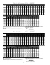
Table 22 — Filter Switch Dirty Set Point
FILTER TYPE
INCREASED
PRESSURE DROP
TO ‘‘DIRTY’’
FROM PIVOT
POINT
APPROXIMATE
CLOCKWISE
TURNS
2-in. Throwaway 0.30 in. wg 2
4-in. Pleated with
2-in. Throwaway
0.75 in. wg 5
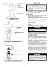
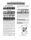
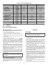
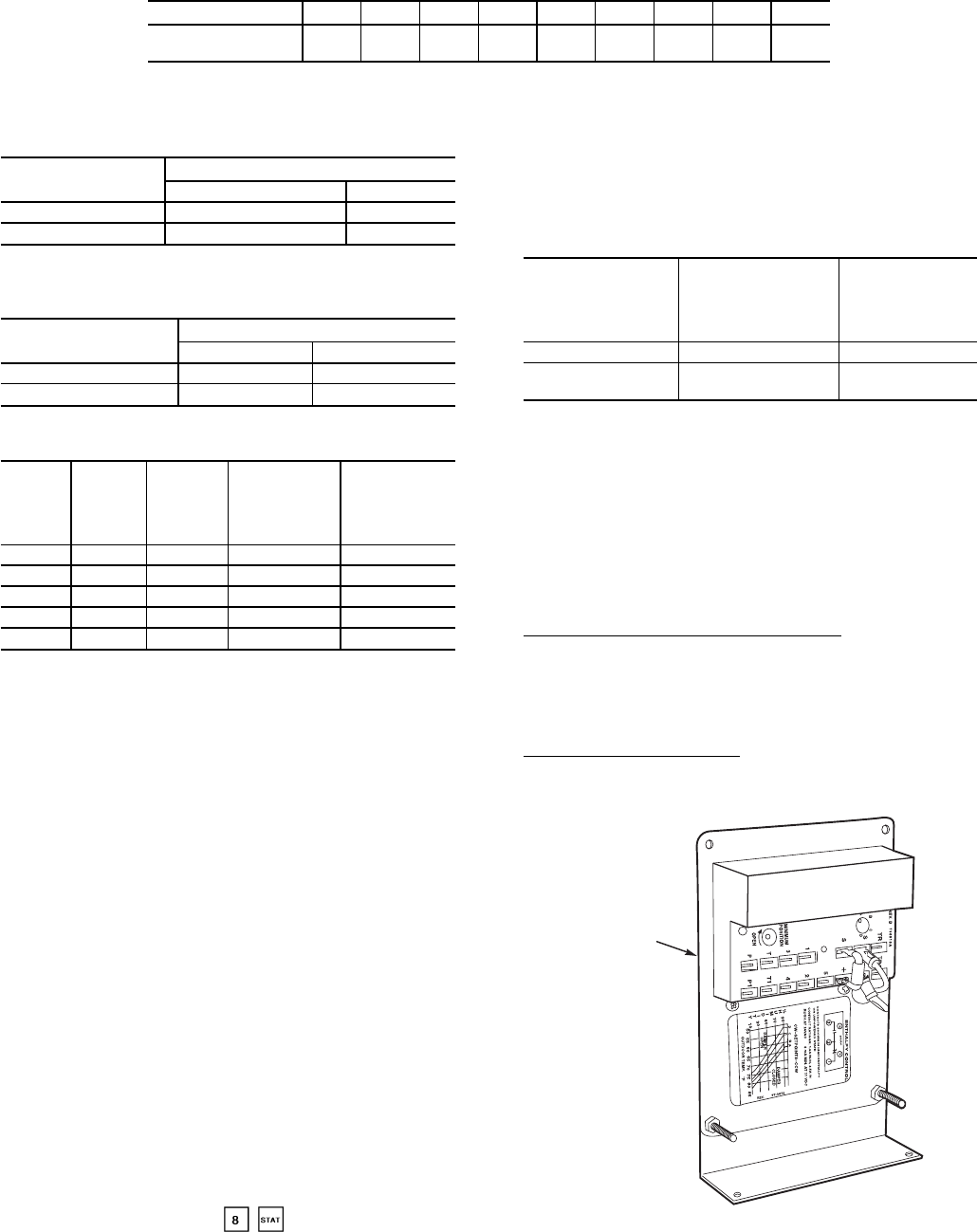
ENTHALPY CONTROL SET POINT — The enthalpy sen-
sor (See Fig. 45) is located behind the filters in the right side
economizer hood and is accessed through the filter access
door. For maximum benefit of outdoor air, set enthalpy sen-
sor control to the A setting. At this setting, when the relative
humidity is 50%, and the outdoor air is below 74 F, the sen-
sor’s relay contacts will be closed. See Fig. 46 and 47.
NOTE: Enthalpy control setting dial is on the enthalpy
control.
Economizer Damper Linkage Adjustment — When replac-
ing economizer damper motors, or if the linkage has come
loose, it is critical that the linkages be adjusted correctly.
They are sensitive, and incorrect adjustment can cause the
motor to stall. Check linkage for free movement and com-
plete range of travel.
Minimum Position Set Point — Minimum economizer po-
sition is set using the keypad and display module. Refer to
Control and Troubleshooting literature for more details.
O
ENTHALPY
SENSOR
Fig. 45 — Enthalpy Sensor
35