General
NOTE: If unit is equipped with REMOTE START function,
place the LOCAL/REMOTE switch in the LOCAL (Off)
position.
1. Put the ON/OFF switch in the ON position. Close the con-
trol circuit breaker (CCB), which will energize the con-
trol circuit and the crankcase heaters.
2. Using the HSIO or Building Supervisor, verify that no
alarms have been detected.
3. Ensure that quick test has been performed to make sure
that the controls are operating properly. Refer to the Con-
trols and Troubleshooting Guide for more information.
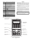
4. Using the HSIO, put the unit into Run mode.
a. Press .
b. Press .
CLEAR
c. Press . This will put the unit in Run mode.
d. Press . The unit will change from mode 25
(standby), to mode 32 (occupied) or mode 27 (unoc-
cupied) depending on the programmed time
schedule.
Operating Sequences — Base unit operating
sequences are presented below. Refer to unit Controls and
Troubleshooting literature for expanded details on unit con-
trols operation, additional controls functions, and logic theory.
SUPPLY FAN
VAV Units — During Occupied periods, the control will en-
ergize the supply fan contactor. The contactor will close,
energizing supply fan motor. Fan wheel will turn. Airflow
Switch (differential pressure switch) contacts close, provid-
ing discrete input (DI) to Channel 12 (Closed = Fan ON).
Fan operation will continue through the Occupied period.
During Unoccupied period with demand, the control will
energize fan contactor when demand is sensed.After fan sta-
tus is confirmed, operating routines will start. When demand
is removed, routines will end and fan will shut off.
CV Units, Continuous Fan — During Occupied periods, the
control will energize the supply fan contactor. The contactor
will close, energizing supply fan motor. Fan wheel will turn.
Airflow Switch (differential pressure switch) contacts close,
providing discrete input (DI) to Channel 12 (Closed =
Fan ON). Fan operation will continue through the Occupied
period.
During Unoccupied period with demand, the control will
energize fan contactor when demand is sensed.After fan sta-
tus is confirmed, operating routines will start. When demand
is removed, routines will end and fan will shut off.
CV Units, Automatic Fan — Fan will be turned OFF during
Occupied period when there is no demand for heating or cool-
ing operation. When demand is sensed, control will energize
fan contactor and initiate cooling cycle. Fan status will be
confirmed. When demand is removed, routines will termi-
nate and fan will be shut off.
ECONOMIZER — The economizer control loop will be de-
layed 2 minutes after the supply fan is turned ON, to allow
system and temperatures to stabilize before starting control.
When coming out of STANDBYor Heating mode, a 4-minute
delay will occur before the economizer damper is con-
trolled. During thisdelay, damper position islimited to CLOSED
or MINIMUM position (depending on current unit occu-
pancy status).
If fan status is OFF, the outside air dampers will remain
closed (return air dampers will be open). If fan status is ON,
the outside air dampers will normally be at minimum damper
position.
Economizer operation is permitted if the system is not in
Heating mode, if outdoor air enthalpy (via switch or humid-
ity differential) is acceptable, and if outside air temperature
is less than space temperature.
If economizer operation is permitted, the ecomizer con-
trol loop checks for Cooling System operation. If ON, the
outside air dampers will be driven to maximum position.
If cooling is not on , for VAV units, the economizer will
modulate to satisfy the supply air set point.
If cooling is not on, for CV units, the economizer will
modulate to satisfy the space temperature set point.
If Economizer operation is not permitted, the outside air
dampers will be driven to minimum position (during Occu-
pied period) or closed (during Unoccupied period).
For VAV units, Economizer operation isnot permitted when
Occupied Heating is enabled and the Return Air Tempera-
ture is LESS THAN (OHSP + 1).
COOLING (All Units)— The controls tryto control the supply-
air temperature (SAT) to a system-calculated coil reference
temperature value by cycling the compressors and the
unloader(s). Both the supply- and return-air temperature sen-
sors are used to adjust the cycling deadband to match the
actual load. The control system provides cooling capacity
control of up to 11 stages to maintain supply-air temperature
(VAV) or space temperature (CV) to an occupied or un-
occupied set point. Automatic lead-lag circuit switching
occurs (if configured) to equalize run times per compressor
for improved compressor reliability. The compressor to start
first is changed every time stage equals zero.
NOTE:Automatic lead/lag should be disabled if optional hot
gas bypass is employed because the unit only contains hot
gas bypass on one circuit.
The VAV controlsystem sequence uses the modified supply-
air set point (MSAT = supply-air set point ϩ reset value) as
the supply-air temperature required to satisfy conditions (sub-
master reference value [CSSR]) and outputs this value to the
submaster loop.
The submaster loop uses the modified supply-air set point
compared to the actual supply-air temperature to determine
the required number of capacity stages to satisfy the load.
The logic for determining when to add or subtract a stage is
a time-based integration of the deviation from the set point
plus the rate of change of the supply-air temperature.
The CV control system sequence reads the space sensor
and performs a calculation to determine the supply-air tem-
perature required (a cooling coil submaster reference [CCSR]
value) to satisfy conditions and outputs this value to the sub-
master loop.
OCCUPIED COOLING
General — Economizer cycle must not be usable or damper
position must be open to 90% or higher.
VAV Units — Supply fan must be ON for cooling control to
operate. Sequence is as follows:
1. Unit must not be in Heating mode.
2. Master Loop will survey occupancy status, Supply Air
Set Point (SASP) and any Supply Air Temperature Reset
command, then issue Cooling Coil Submaster Reference
(CCSR) to Cooling Submaster Loop (CSL).
3. The CSL surveys actual SAT, then calculates number of
capacity stages required to produce the CCSR leaving the
unit.
4. Stages of cooling capacity are initiated. From zero stages,
there will be a 1.5 to 3 minute delay before the first stage
is initiated. The time delay between stages in increasing
demand is 90 seconds.
39


