


11. Check supply fan belts, sheaves, and bearings. Check
the lubrication of the fan and motor bearings. Check bear-
ing and bearing set screws for tightness. Check sheave
alignment and belt tension. Hand turn fan to ensure fan
wheel does not rub on housing. The fan shaft and motor
shaft must turn freely before power is applied to the unit.
12. Check exhaust fan belts, sheaves, and bearings. Check
the lubrication of the fan and motor bearings. Check bear-
ing and bearing set screws for tightness. Check sheave
alignment and belt tension. Hand turn fan to ensure fan
wheel does not rub on housing.
13. Check economizer linkage. Economizer dampers should
be fully closed. Linkage should permit full and free travel.
14. Check that the correct return air filters are installed in
the filter tracks. Do not operate unit without return air
filters.
15. Check that all access doors on the air handler section
have been closed and secured.
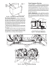
16. Fan motors are 3-phase. Check rotation of fans during
first start-up check. Fan rotation is clockwise as viewed
from top of unit. If fan is not turning clockwise, reverse
2 of the power wires.
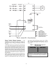
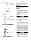
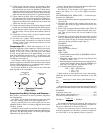
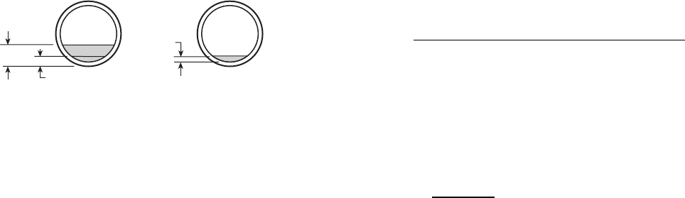
Compressor Oil — Check that compressor oil is vis-
ible in the sight glass of the compressor. All units are factory
charged with oil. See Table 3. Observe oil level closely at
start-up. If oil level is below the sight glass and cannot
be seen, add oil until the level is approximately
3
⁄
8
to
1
⁄
8
of
sight glass (06E-299 compressors are
1
⁄
8
of sight glass). See
Fig. 44. See Oil Charge section on page 49 for information
on adding or removing oil.
If oil charge is above sight glass, do not remove any oil
until the compressor crankcase heater has been on for at least
24 hours. When additional oil or a complete charge is needed,
use only Carrier-approved compressor oil.
Do not reuse drained oil and do not use any oil that has
been exposed to the atmosphere.
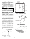
Evaporator-Fan Belts, Pulleys, and Sheaves —
Belts, pulleys, and sheaves are factory installed. All pulleys
are nonadjustable.
See Table 1 for fan shaft center distance ranges and shaft
sizes when making selections for field-supplied drives.
Factory-installed drives are fixed-speed and are non-
adjustable. Refer to Table 1 for factory-supplied wheel speeds
and drive set data.
If different wheel speeds are required for an application,
Carrier recommends thatthe installer contact the nearestBrown-
ing dealer. The Browning dealer can develop the required
information for the fan drive set.
Observe the maximum wheel speed and unit airflow lim-
its for the specific unit size and fan type.
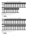
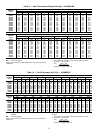
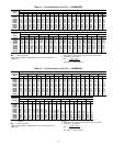
See Tables 8-12 for forward curve supply fan perfor-
mance. See Tables 13-17 for air foil supply fan perfor-
mance.
FAN PERFORMANCE, 48MP UNITS — To obtain fan per-
formance for 48MP units:
1. Enter fan performance table for appropriate base unit type
and unit size.
2. Determine the external static pressure from the fan per-
formance table using fan type, field-measured rpm, and
airflow (cfm).
3. Refer to the Component Pressure Drops table (Table 18)
on page 35. Calculate the adjusted external static pres-
sure value for the correct unit size and airflow for gas
heat units.
4. Calculate the net external static pressure for the gas heat
units by subtracting the adjusted external static pressure
value from Table 18 (Step 3) from the external static pres-
sure from the fan performnce table (Step 2).
EXAMPLE:
Field Measurements:
Unit: 48MP62L
Fan Type: Forward Curved
RPM: 500
CFM: 22,000
1. Select Fan Performance Table 8, 48/50MP62Lwith For-
ward Curved fan.
2. Determine external static pressure using 500 rpm and
22,000 cfm. ESP = 1.25.
3. Read the adjusted external static pressure from theCom-
ponent Static Pressure Drops table for 48MP62L gas
heat units at 22,000 cfm. Adjusted ESP = 0.31.
4. Calculate external static pressure.
ESP = ESP − ESP Adjusted
= 1.25 − 0.31
= 0.94 in. wg
Check rotation of wheel with arrow on the fan housing.
Check fan speed with a strobe-type tachometer, or use this
formula:
motor rpm x motor sheave pitch diameter (in.)
Fan
=
Rpm
fan sheave pitch diameter (in.)
(Obtain motor rpm from the fan motor nameplate and read
sheave pitch diameters marked on the fan and motor sheaves.)
EXAMPLE:
Nameplate motor rpm .........................1760
Motor sheave pitch diameter (in.) .................6.4
Fan sheave pitch diameter (in.) ..................12.4
1760 x 6.4
Fan Rpm = = 908 Rpm
12.4
The maximum allowable fan speed for the supply fan is
shown in Table 19. The maximum allowable fan speed for
the power exhaust fan is shown in Table 20.
Excessive fan speed may result in condensate carryover
from the evaporator coil, fan motor overload, or wheel fail-
ure. See Table 21 for Air Quantity Limits on page 35.
1/8
1/8
3/8
COMPRESSOR
06E
(EXCEPT 06E-299)
COMPRESSOR
06E-299
Fig. 44 — Operating Oil Levels
(Sight Glass)
29