


If flexible connector is required or allowed by authority
having jurisdiction, black iron pipe shall be installed at gas
valve and extend a minimum of 2 in. outside furnace casing.
Use the proper length of pipes to avoid stress on gas control
manifold. A failure to follow this warning could result in a
gas leak causing fire, explosion, personal injury, or death.
Use a backup wrench at furnace gas control when connecting
gas pipe to furnace to avoid damaging gas controls or
manifold.
Never purge a line into a combustion chamber. Never use
matches, candles, flame, or other sources of ignition to check
for gas leakage. Use a soap-and-water solution to check for
gas leaks. A failure to follow this warning could result in fire,
explosion, personal injury, or death.
Joint compounds (pipe dope) should be applied sparingly and only
to male threads of joints. This pipe dope must be resistant to action
of propane gas.
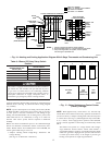
Install accessible manual shutoff valve upstream of furnace gas
controls and within 72 in. of furnace. A 1/8-in. NPT plugged
tapping is provided on gas value for test gage connection.
Installation of additional 1/8-in. NPT plugged tapping, accessible
for test gage connection, installed immediately upstream of gas
supply connection to furnace and downstream of manual shutoff
valve is not required. Place ground joint union between gas control
manifold and manual shutoff.
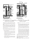
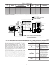
Install sediment trap in riser leading to furnace. The trap can be
installed by connecting a tee to riser leading from furnace. Connect
capped nipple into lower end of tee. The capped nipple should
extend below level of gas controls. (See Fig. 13.)
Piping should be pressure tested in accordance with local and
national plumbing and gas codes before furnace has been attached.
If test pressure exceeds 0.5 psig (14-in. wc), the gas supply pipe
must be disconnected from furnace and capped before pressure
test. If test pressure is equal to or less than 0.5 psig (14-in. wc),
turn off electric shutoff switch located on the gas valve before test.
(See Fig. 13.) It is recommended that ground joint union be
loosened before pressure testing.
After all connections have been made, purge lines and check for
gas leakage with regulated gas supply pressure.
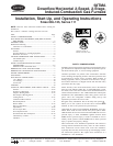
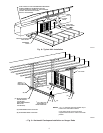
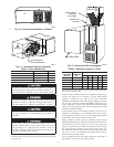
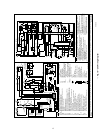
Fig. 10—Horizontal Installation on Blocks
A95235
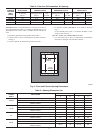
Table 4—Filter Retainer (In.)
FURNACE CASING WIDTH FILTERS D
14-3/16 (2) 14 X 20 X 1 14-3/8
17-1/2 (2) 14 X 20 X 1 13-3/8
21 (2) 16 X 20 X 1 11-5/8
24-1/2 (2) 16 X 20 X 1 10-1/4
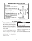
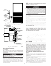
Fig. 11—Horizontal Filter Arrangement
A82173
FIELD-SUPPLIED
FILTER RETAINERS
AIRFLOW
D
12″
4″
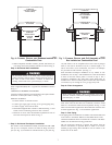
Fig. 12—Downflow Filter Arrangement
A88486
RETURN-AIR
PLENUM
AIRFLOW
ACCESS DOOR
INSTALLATION
POSITION
OF FILTERS
Table 5—Maximum Capacity of Pipe*
NOMINAL
IRON PIPE
SIZE (IN.)
INTERNAL
DIAMETER
(IN.)
LENGTH OF PIPE (FT)
10 20 30 40 50
1/2 0.622 175 120 97 82 73
3/4 0.824 360 250 200 170 151
1 1.049 680 465 375 320 285
1-1/4 1.380 1400 950 770 660 580
1-1/2 1.610 2100 1460 1180 990 900
* Cubic ft of gas per hr for gas pressures of 0.5 psig (14-in. wc) or less, and a
supply line pressure drop of 0.5-in. wc (based on a 0.60 specific gravity gas).
Ref: Table 10-2, NFPA 54-1996.
9
→