


a. Place duct thermometers in return and supply ducts as near
furnace as possible. Be sure thermometers do not see heat
exchangers so that radiant heat will not affect thermometer
readings. This is particularly important with straight-run
ducts.
b. When thermometer readings stabilize, subtract return-air
temperature from supply-air temperature to determine tem-
perature rise.
NOTE: If temperature rise is outside this range, first check:
(1.) Gas input for low- and high-heat operation.
(2.) Derate for altitude if applicable.
(3.) Return and supply ducts for excessive restrictions
causing static pressures greater than 0.50-in. wc.
c. Adjust air temperature rise by adjusting blower speed.
Increase blower speed to reduce temperature rise. Decrease
blower speed to increase temperature rise. For high heat,
speed selection can be med-high, med (5-speed blowers
only), or med-low (factory setting). For low heat, speed tap
selection can be low (factory setting), med-low, or med
(5-speed blowers only).
Disconnect electrical power before changing speed tap (or
removing motor lead cap if used on 5-speed motors). A
failure to follow this warning can cause personal injury or
death.
NOTE: For furnaces with 5-speed motors, ensure that unused
speed tap is either capped or, placed on SPARE terminalon control
board before power is restored.
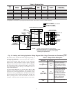
d. To change motor speed selection for high heat, remove
blower motor lead from control HIGH-GAS-HEAT termi-
nal. (See Fig. 14 and Fig. 18.) Select desired blower motor
speed lead from 1 of the other terminals and relocate it to
HIGH-GAS-HEAT terminal. See Table 11 for lead color
identification. Reconnect original lead to SPARE terminal
(or use insulating cap, if used, applies only to furnaces with
5-speed blower motors). Follow this same procedure for
proper selection of cool and low-gas-heat speed selection.
6. Set thermostat heat anticipator.
a. When using a nonelectronic thermostat, the thermostat heat
anticipation must be set to match amp draw of electrical
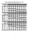
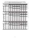
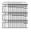
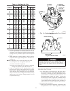
Table 11—Gas Rate (Cu Ft/Hr)
SECONDS
FOR 1
REVOLUTION
SIZE OF TEST DIAL
SECONDS
FOR 1
REVOLUTION
SIZE OF TEST DIAL
1
cu ft
2
cu ft
5
cu ft
1
cu ft
2
cu ft
5
cu ft
10
11
12
13
14
360
327
300
277
257
720
655
600
555
514
1800
1636
1500
1385
1286
50
51
52
53
54
72
71
69
68
67
144
141
138
136
133
360
355
346
340
333
15
16
17
18
19
240
225
212
200
189
480
450
424
400
379
1200
1125
1059
1000
947
55
56
57
58
59
65
64
63
62
61
131
129
126
124
122
327
321
316
310
305
20
21
22
23
24
180
171
164
157
150
360
343
327
313
300
900
857
818
783
750
60
62
64
66
68
60
58
56
54
53
120
116
112
109
106
300
290
281
273
265
25
26
27
28
29
144
138
133
129
124
288
277
267
257
248
720
692
667
643
621
70
72
74
76
78
51
50
48
47
46
103
100
97
95
92
257
250
243
237
231
30
31
32
33
34
120
116
113
109
106
240
232
225
218
212
600
581
563
545
529
80
82
84
86
88
45
44
43
42
41
90
88
86
84
82
225
220
214
209
205
35
36
37
38
39
103
100
97
95
92
206
200
195
189
185
514
500
486
474
462
90
92
94
96
98
40
39
38
38
37
80
78
76
75
74
200
196
192
188
184
40
41
42
43
44
90
88
86
84
82
180
176
172
167
164
450
439
429
419
409
100
102
104
106
108
36
35
35
34
33
72
71
69
68
67
180
178
173
170
167
45
46
47
48
49
80
78
76
75
73
160
157
153
150
147
400
391
383
375
367
110
112
116
120
33
32
31
30
65
64
62
60
164
161
155
150
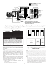
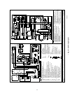
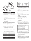
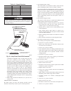
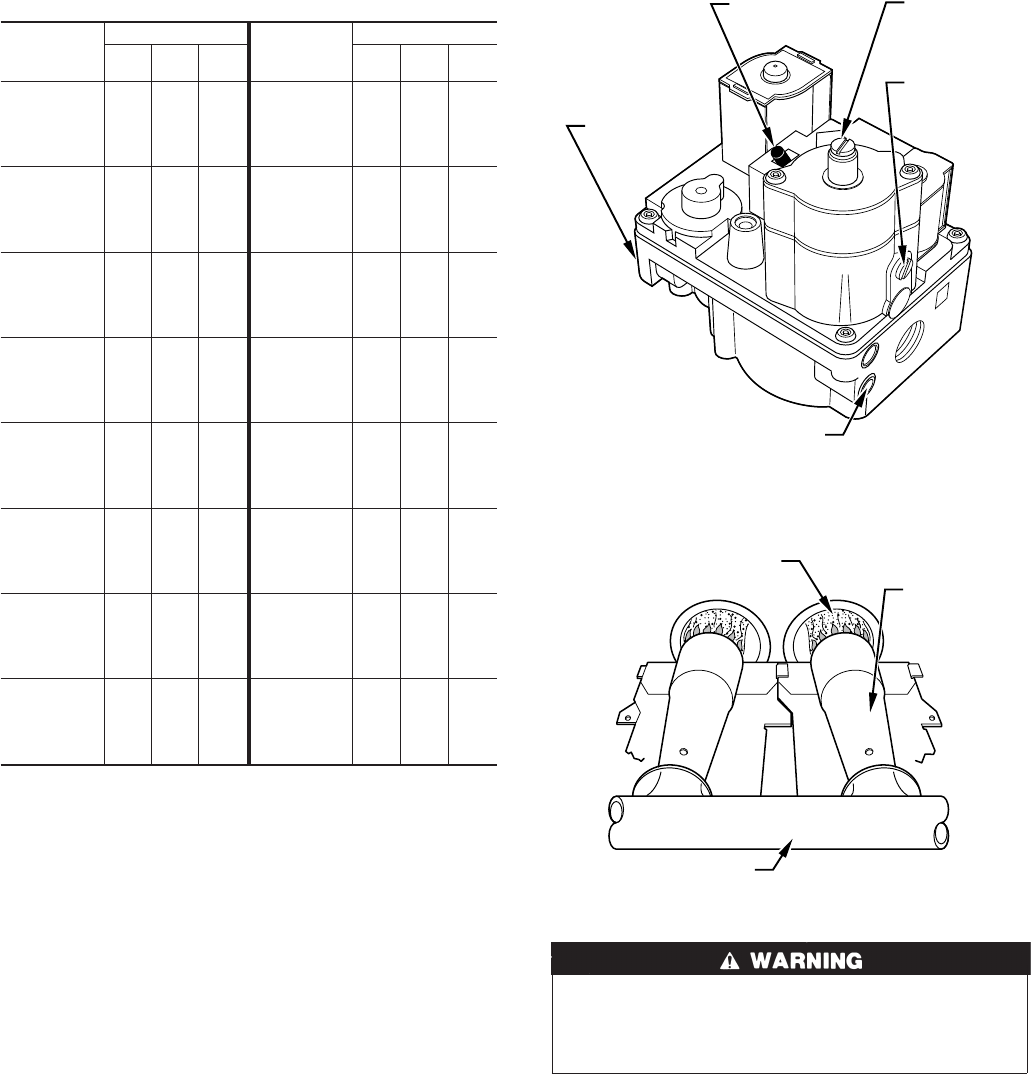
→ Fig. 19—Redundant Automatic Gas Control
Valve
A97358
ON/OFF
SWITCH
INLET
PRESSURE
TAP
ON
O
F
F
MANIFOLD
PRESSURE
TAP
LOW-FIRE
ADJUSTMENT
ALLEN SCREW
(UNDER CAP)
HIGH-FIRE
ADJUSTMENT
ALLEN SCREW
(UNDER CAP)
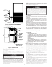
Fig. 20—Burner Flame
A89020
BURNER FLAME
BURNER
MANIFOLD
21