


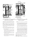
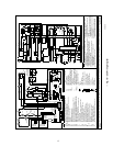
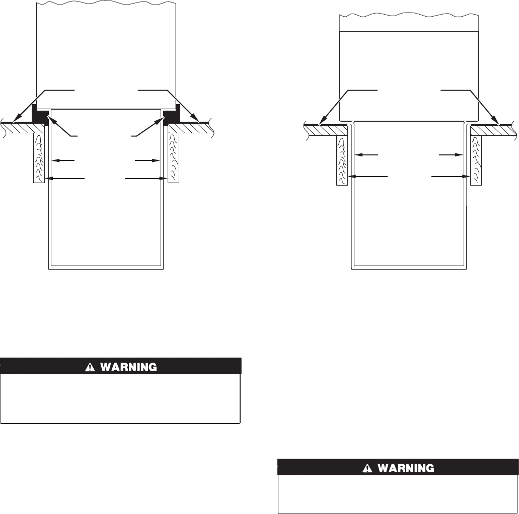
2. When completed, downflow subbase, plenum, and furnace (or
coil casing when used) should be installed as shown in Fig. 6.
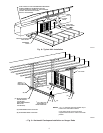
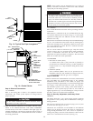
Step 4—Horizontal Attic Installation
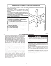
Do not install furnace on its back; safety control operation
will be adversely affected. Never connect return-air ducts to
the sides or back of the furnace. A failure to follow this
warning could result in fire, personal injury, or death.
The furnace can be installed horizontally on either the left-hand
(LH) or right-hand (RH) side. A typical attic installation is shown
in Fig. 8.
CONSTRUCT WORKING PLATFORM
Construct working platform on location where all required furnace
clearances are met. (See Table 1 and Fig. 8.)
INSTALL FURNACE
1. Position furnace in desired location.
2. Connect gas supply pipe. See Fig. 8 for typical piping entry.
3. Connect supply- and return-air ducts.
4. Install field-supplied filter retainers as indicated in Fig. 11 and
Table 4 before connecting return-air duct to furnace.
5. Install 24- X 24-in. sheet metal shield on platform in front of
louvered control panel as shown in Fig. 8.
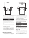
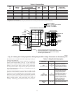
Step 5—Horizontal Crawlspace Installation
The furnace can be installed horizontally with either the LH or RH
side up. In a crawlspace, furnace can either be hung from floor
joist (see Fig. 9) or installed on suitable blocks or pad. (See Fig.
10.) The furnace can be suspended from each corner by hanger
bolts (4 each 3/8-in. all-thread rod) cut to desired length, 1- X
3/8-in. flat washer, 3/8-in. lockwasher, and 3/8-in. nut. Dimples
are provided for hole locations. (See Fig. 1.)
Since horizontal crawlspace installation is very similar to attic
installation, refer to Step 4. The installation of a sheet metal shield
in front of louvered control panel is covered in Step 4. For a
crawlspace installation, this same sheet metal shield must be
installed above louvered control panel. Extend sheet metal shield
over furnace top far enough to cover gas pipe entry hole.
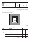
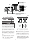
Step 6—Filter Arrangement
Never operate unit without a filter or with filter access door
removed. A failure to follow this warning could result in fire,
personal injury, or death.
The 2 factory-supplied filters are shipped in the blower compart-
ment. After return-air duct has been connected to furnace, install
filters in a V-formation inside return-air plenum. See Fig. 11 and
Table 4 for horizontal applications. Horizontal filter retainers must
be field supplied. See Fig. 12 for downflow applications.
Step 7—Gas Piping
Gas piping must be installed in accordance with national and local
codes. Refer to the NFGC NFPA 54-1996/ANSI Z223.1-1996.
Canadian installations must be installed in accordance with NSC-
NGPIC and all authorities having jurisdiction.
The gas supply line should be a separate line directly from the
meter to the furnace, if possible. Refer to Table 5 for recom-
mended gas pipe sizing. Risers should be used to connect to the
furnace and to the meter.
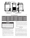
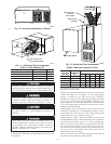
Fig. 6—Furnace, Plenum, and Subbase Installed on
Combustible Floor
A96285
DOWNFLOW
SUBBASE
SHEET METAL
PLENUM
FLOOR
OPENING
FURNACE
(OR COIL CASING
WHEN USED)
COMBUSTIBLE
FLOORING
Fig. 7—Furnace, Plenum, and Coil Assembly or Coil
Box Installed on Combustible Floor
A96284
CD5 OR CK5
COIL ASSEMBLY
OR KCAKC
COIL BOX
FURNACE
SHEET METAL
PLENUM
FLOOR
OPENING
COMBUSTIBLE
FLOORING
7
→
→