


BLWM operation at heat pump heating speed until end of
prepurge period, then shuts off until end of HSI ignitor on
period (22 sec).
b. When installed with a heat pump, furnace control CPU
automatically holds blower off time to 22 sec during HSI
ignitor on period. After 17 sec of HSI ignitor on period, a
trial-for-ignition sequence occurs as described above for
gas heating. After flame is proved and without blower on
delay, blower motor BLWM then operates on high-gas-
heat speed during defrost. For both single-speed and
2-speed heat pumps, defrost mode is in high-gas heat only.
c. When furnace control R to W/W1 circuit is opened, furnace
control CPU begins normal inducer post-purge period, and
blower motor BLWM remains on for blower off delay
period. If R-G circuit remains closed, blower motor
BLWM reverts to continuous operation.
START-UP PROCEDURES
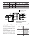
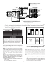
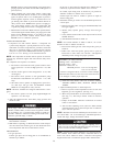
1. Component test—The furnace features a component test
system to help diagnose a system problem in case of compo-
nent failure. To initiate component test procedure, ensure that
there are no thermostat inputs to control and that all time
delays have expired. Short TWIN/TEST terminal to ground or
C
OM for 1 to 4 sec. See Fig. 14 for terminal locations.
NOTE: The component test feature will not operate if control is
receiving any thermostat signals and until all time delays have
expired.
The component test sequence is as follows:
a. The furnace control checks itself, operates inducer motor
on low speed for 7 sec and on high speed for 7 sec, then
stops.
b. The hot surface ignitor is then energized for 15 sec, then
de-energized.
c. The blower motor operates on low-gas-heat/heat pump
low-heat/low-cool/continuous fan speed for 7 sec, then
stops.
d. The blower motor operates on high-gas-heat speed for 7
sec, then stops. The gas valve and humidifier terminal
HUM are not energized for safety reasons.
NOTE: The EAC terminals are energized when blower is ener-
gized.
e. The blower operates on heat pump high-heat/high-cool
speed for 7 sec, then stops.
2. After all connections have been made, purge gas lines and
check for leaks.
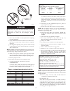
Never purge a line into a combustion chamber. Never use
matches, candles, flame, or other sources of ignition to check
for gas leakage. Use a soap-and-water solution to check for
gas leaks. A failure to follow this warning could result in fire,
explosion, personal injury, or death.
3. To operate furnace, follow procedures on operating instruction
label attached to furnace.
4. With furnace operating, set thermostat below room tempera-
ture and observe that furnace goes off. Set thermostat above
room temperature and observe that furnace restarts.
ADJUSTMENTS
1. Set gas input rate.
Furnace gas input rate on rating plate is for installations at
altitudes up to 2000 ft.
In the U.S.A., input rating for altitudes above 2000 ft must be
reduced by 4 percent for each 1000 ft above sea level.
In Canada, input rating must be derated by 10 percent for
altitudes of 2000 ft to 4500 ft above sea level.
Furnace input rate must be within ±2 percent of input on
furnace rating plate.
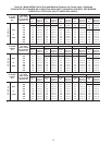
2. Determine natural gas orifice size and manifold pressure for
correct input.
a. Obtain yearly heat value average (at installed altitude) from
local gas supplier.
b. Obtain yearly specific gravity average from local gas
supplier.
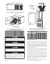
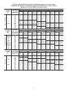
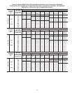
c. Verify furnace model. Table 10 can only be used for model
58TMA Furnaces.
d. Find installation altitude in Table 10.
NOTE: For Canada altitudes of 2000 to 4500 ft, use U.S.A.
altitudes of 2001 to 3000 ft in Table 10.
e. Find closest natural gas heat value and specific gravity in
Table 10.
f. Follow heat value and specific gravity lines to point of
intersection to find orifice size and low- and high-heat
manifold pressure settings for proper operation.
EXAMPLE: (0—2000 ft altitude)
Heating value = 1075 Btu/cu ft
Specific gravity = 0.62
Therefore: Orifice No. 45
Manifold pressure: 3.7-in. wc for high heat
1.5-in. wc for low heat
* Furnace is shipped with No. 45 orifices. In this example,
all main burner orifices are the correct size and do not need
to be changed to obtain proper input rate.
g. Check and verify burner orifice size in furnace. NEVER
ASSUME ORIFICE SIZE; ALWAYS CHECK AND
VERIFY.
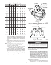
3. Adjust manifold pressure to obtain input rate.
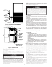
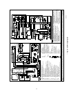
a. Remove caps that conceal adjustment screws for low- and
high-heat gas valve regulators. (See Fig. 19.)
b. Move setup switch SW-2 on control center to ON position.
(See Fig. 17.) This keeps furnace locked in low-heat
operation.
c. Jumper R and W/W1 thermostat connections on control
center to start furnace.
d. Turn low-heat adjusting screw (5/64 hex Allen wrench)
counterclockwise (out) to decrease input rate or clockwise
(in) to increase input rate.
NOTE: DO NOT set low-heat manifold pressure less than 1.3-in.
wc or more than 1.7-in. wc for natural gas. If manifold pressure is
outside this range, change main burner orifices.
DO NOT bottom out gas valve regulator adjusting screw.
This can result in unregulated manifold pressure and result in
excess overfire and heat exchanger failures.
NOTE: If orifice hole appears damaged or it is suspected to have
been redrilled, check orifice hole with a numbered drill bit of
correct size. Never redrill an orifice. A burr-free and squarely
aligned orifice hole is essential for proper flame characteristics.
16