


in alcoves, attics, crawlspaces, basements, closets, or utility rooms.
The design of this furnace line is not A.G.A./C.G.A. certified for
installation in mobile homes, recreation vehicles, or outdoors.
Before installing the furnace, refer to the current edition of the
NFGC and the NFPA 90B. Canadian installations must beinstalled
in accordance NSCNGPIC and all authorities having jurisdiction.
For a copy of the NFGC NFPA54/Z223.1, contact International
Approval Services U.S. Inc., 8501 E. Pleasant Valley Road,
Cleveland, OH 44131 or National Fire Protection Association Inc.,
Batterymarch Park, Quincy, MA 02269. For a copy of NFPA 90B,
contact National Fire Protection Association Inc., Batterymarch
Park, Quincy, MA 02269.
Before installing the furnace in Canada, refer to the current edition
of the NSCNGPIC. Contact Standards Department of Canadian
Gas Association, 55 Scarsdale Road, Don Mills, Ontario, Canada
M3B 2R3.
The duct system should be designed and sized according to
accepted national standards published by: Air Conditioning Con-
tractors Association (ACCA), Sheet Metal and Air Conditioning
Contractors National Association (SMACNA). Or consult the
Residential Systems Design Guidelines reference tables available
from your local distributor. The duct system should be sized to
handle the maximum CFM capabilities of the equipment at the
optimum design static pressure.
Application of this furnace should be indoors with special
attention given to vent sizing and material, gas input rate, air
temperature rise, and unit sizing. Improper installation or
misapplication of the furnace can require excessive servicing
or cause premature component failure.
Installation must conform to regulations of serving gas supplier
and local building, heating, and plumbing codes in effect in the
area in which installation is made, or in absence of localcodes with
requirements of the NFGC.
This furnace is designed for a minimum continuous return-air
temperature of 60°F db or intermittent operation down to 55°F
such as when used with a night setback thermostat. Return-air
temperature must not exceed 85°F db.
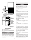
To aid in installation, troubleshooting, and service, a status code
label is located on blower component door. This label explains
how to use the LED status indicated on furnace control which is
viewed through the sight glass on door.
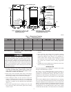
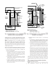
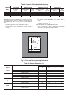
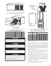
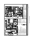
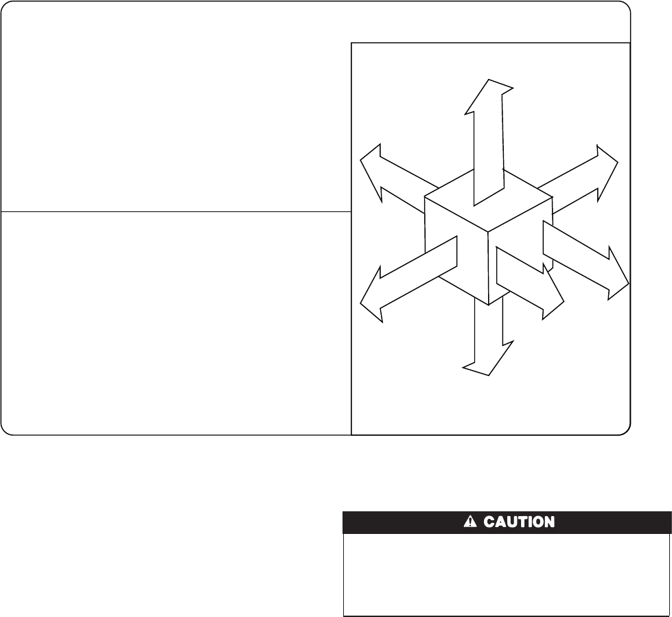
Fig. 2—Clearances to Combustibles
A97430
322286-101 REV. D (LIT)
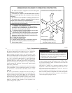
MINIMUM INCHES CLEARANCE TO COMBUSTIBLE CONSTRUCTION
This forced air furnace is equipped for use with natural gas at
altitudes 0-10,000 ft (0-3,050m).
An accessory kit, supplied by the manufacturer,shall be used to
convert to propane gas use or may be required for some natural gas
applications.
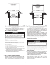
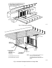
This furnace is for indoor installation in a building constructed on site.
This furnace may be installed on combustible flooring in alcove or
closet at minimum clearance from combustible material.
This furnace may be used with a Type B-1 Vent and may be vented
in common with other gas-fired appliances.
Ø
†
*
For installation on non-combustible floors only.
For installation on combustible flooring only when installed on
special base, Part No. KGASB0201ALL, Coil Assembly, Part No.
CD5 or CK5, or Coil Casing, Part No. KCAKC.
For furnaces wider than 14.25 inches (362mm) may be 0 inches.
18 inches front clearance required for alcove.
Indicates supply or return sides when furnace is in the horizontal
position. Line contact only permissible between lines formed by
intersections of the Top and two Sides of the furnace jacket, and
building joists, studs or framing.
For single wall vent type 6 inches.
For Type B-1 vent type 3 inches.
Clearance to Back 0 inches (0 po) in downflow and horizontal
(attic/alcove & crawlspace) positions and 3 inches (3 po) in
horizontal closet positions.
#
Clearance in inches.
Clearance arrows do not change with furnace orientation.
BOTTOM
1
"
#
##
1" #
0"
††
1"
1"
30"
MIN
S
I
D
E
F
R
O
N
T
B
C
K
A
S
E
R
V
I
E
C
F
R
O
N
T
S
I
E
U
F
R
N
A
C
E
##
††
#
Ø
Vent Clearance to combustibles:
For Single Wall vents 6 inches (6 po).
For Type B-1 vent type 1 inch (1 po).
TOP / PLENUM
D
*
*
†
3
→