


Step 8—Electrical Connections
115-V WIRING
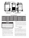
Refer to unit rating plate or Table 6 for equipment electrical
requirements. The control system requires an earth ground for
proper operation.
Do not connect aluminum wire between disconnect switch
and furnace. Use only copper wire.
Make all electrical connections in accordance with the current
edition of the National Electrical Code (NEC) ANSI/NFPA
70-1996 and any local codes or ordinances that might apply. For
Canadian installations, all electrical connections must be made in
accordance with CSA C22.1 Canadian Electrical Code or authori-
ties having jurisdiction.
NOTE: Proper polarity must be maintained for 115-v wiring. If
polarity is incorrect, the furnace control status LED will flash
rapidly and prevent heating operation.
The cabinet must have an uninterrupted or unbroken ground
according to NEC ANSI/NFPA 70-1996 and Canadian Elec-
trical Code CSA C22.1 or local codes to minimize personal
injury if an electrical fault should occur. This may consist of
electrical wire or conduit approved for electrical ground when
installed in accordance with existing electrical codes. Do not
use gas piping as an electrical ground.
24-V WIRING
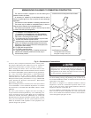
Refer to ESD Precautions Procedure before proceeding with 24-v
connections.
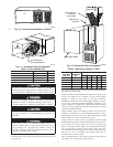
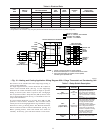
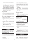
Make field 24-v connections at the 24-v terminal block. (See Fig.
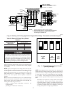
14.) Connect terminal Y/Y2 as shown in Fig. 15 or 16 for proper
operation in cooling mode. Use AWG No. 18 color-coded, copper
thermostat wire only.
When furnace is installed in horizontal position with RH discharge
air, 24-v wire connections can be made easier by removing the 2
control box mounting screws and letting control box turn so that
24-v screw terminals are visible. Be sure to reinstall control box
after connections are made.
The 24-v circuit contains an automotive-type, 3-amp fuse located
on main control. Any 24-v electrical shorts during installation,
service, or maintenance could cause this fuse to blow. If fuse
replacement is required, use ONLY a 3-amp fuse. The control will
flash code 24 when fuse needs replacement.
ACCESSORIES
1. Electronic air cleaner (EAC)
A terminal block (EAC-1 [hot] and EAC-2 [neutral]) is
provided for EAC connection. (See Fig. 14.) The terminals are
energized with 115v, 1-amp maximum during blower motor
operation.
2. Humidifier (HUM)
Screw terminals (HUM-1 and C
OM) are provided for 24-v
humidifier connection. The terminals are energized with 24v,
0.5-amp maximum when the gas valve is energized.
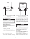
Step 9—VENTING
Refer to National or Local Installation Code such as; National Fuel
Gas Code NFPA No. 54-1996/Z223.1-1996, or the Canadian
Installation Code, CAN B149.1- and .2-M95, for proper vent
sizing and installation requirements. Use enclosed Venting Tables
for Category I Fan-Assisted Furnaces for quick, easy reference.
The horizontal portion of the venting system shall maintain a
minimum of 1/4-in. upward slope per linear ft, and it shall be
rigidly supported every 5 ft or less with hangers or straps to ensure
that there will be no movement after installation.
Step 10—Start-Up, Adjustment, and Safety Check
GENERAL
The furnace must have a 115-v power supply properly connected
and grounded. Correct polarity must be maintained to enable gas
heating operation.
The gas service pressure must not exceed 0.5 psig (14-in. wc), and
be no less than 0.16 psig (4.5-in. wc).
Thermostat wire connections at R and W/W1 are the minimum
required for gas heating operation. W2 must be connected for
2-stage heating thermostats. C
OM, Y/Y2, and G are required for
cooling, heat pumps, and some clock thermostats. These must be
made at 24-v terminal block on control. (See Fig. 14.)
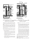
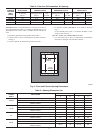
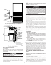
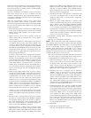
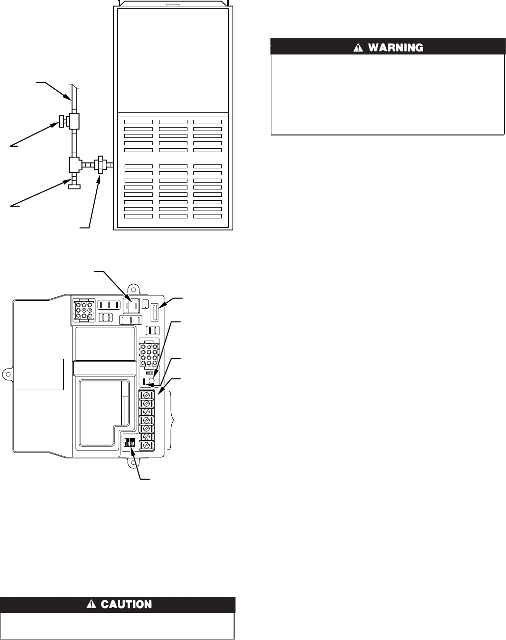
Fig. 13—Typical Gas Pipe Arrangement
A89414
GAS
SUPPLY
MANUAL
SHUTOFF
VALVE
(REQUIRED)
SEDIMENT
TRAP
UNION
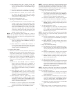
Fig. 14—Control Center
A93348
123
456
789
PR2
L2
COM
PR1
L1
EAC-2
EAC-1
HI-COOL
HI-GAS
-HEAT
LO-GAS
-HEAT
PARK
3
FU1
SEC-1
SEC-2
1
123
456
7
8
9
10 11 12
MASTER SLAVE
TWIN
TEST
LED
GRY/Y2W/W1
COM
24 V
W2
1
ON
OFF
1234
FURNACE AND
BLOWER OFF DELAY
SETUP SWITCHES
24-VOLT
THERMOSTAT
TERMINALS
EAC - ELECTRONIC
AIR CLEANER
(115-VAC 1 AMP MAX)
3-AMP
FUSE
LED -
DIAGNOSTIC
LIGHT
TWIN / TEST
TERMINAL
HUM -
HUMIDIFIER
(24-VAC 0.5
AMP MAX)
HUM
10
→
→
→